Review Article
Austin J Anesthesia and Analgesia.2014;2(2): 1014.
US-Guided Interventions Cervical Spine Injections
JeeYoun Moon1,2,*, Sang Chul Lee1
1Anesthesiology & Pain Medicine, Seoul National University Hospital, Korea
2Integrated Cancer Pain Management Center, Seoul National University Cancer Hospital, Korea
*Corresponding author: JeeYoun Moon, Department of Anesthesiology and Pain Medicine, Seoul National University Hospital College of Medicine, 110 Daehang-ro, Jongno-gu, Seoul, 110-744, Korea.
Received: December 02, 2013; Accepted: January 24, 2014; Published: January 27, 2014
Abstract
Application of ultrasound (US) in pain medicine is a rapidly growing field of interventional pain management and in the recent few years US guidance for spine injections in chronic pain practice has been noticed. The cervical spine is supposed to be a better place to start than the lumbar spine, as US may be more advantageous in the neck for the identification of various critical soft tissue structures, thus making the injection easier and safer. In the present report, we review the known US-guided cervical spine procedures briefly.
Introduction
Ultrasound (US)-guided pain blocks has grown up since 2004 from lumbar and cervical facet nerve blocks (cervical medial branch block, C-MBB) and intra-articular injections [1-3]. This was followed by a renewed interest in US-guided stellate ganglion block [4] and then by rapidly growing interest in the application of US for cervical spine in pain medicine such as cervical nerve root block [5], and recently deep cervical plexus block [6] and atlantoaxial (AA) joint injection [7]. It must be true that the cervical spine is a better place to start than the lumbar spine, as US may be more advantageous in the neck for the identification of various critical soft tissue structures, thus making the injection easier and safer.
It is well known US-guidance appealing for a few points [1,8]: 1) radiation-free imaging. This is especially important with cervical injections. Where there is increased scattered radiation from the c-arm; 2) ability to identify and avoid vessels in the trajectory of the needle; 3) US offers dynamic, real-time imaging of the cervical spine; and 4) Short procedure time and the need to insert only 1 needle (for third occipital nerve blocks).
Recently, in accordance with the remarkable increase in the publication of literatures and the growing number of workshops on US-guided injections, the Joint Committee (ASRA/ESRA/Asian Australasian Federation of Pain Societies and committee members) published a recommendations and training guidelines to provide a structure about proper levels of competency, proficiency, and quality improvement for the safe and the efficacious utilization of US for pain medicine procedures [9]. The Joint Committee assigned level of difficulty for specific US-guided pain interventions -US-guided cervical spine interventions usually belong to the intermediate or advanced level of difficulty.
In the present article, we reviewed the known US-guided cervical spine procedures briefly.
Sonoanatomy of the Cervical Spine for Well-known Cervical Spine Interventions
Identifying the correct cervical spine level [1]
Lower cervical spine procedures:
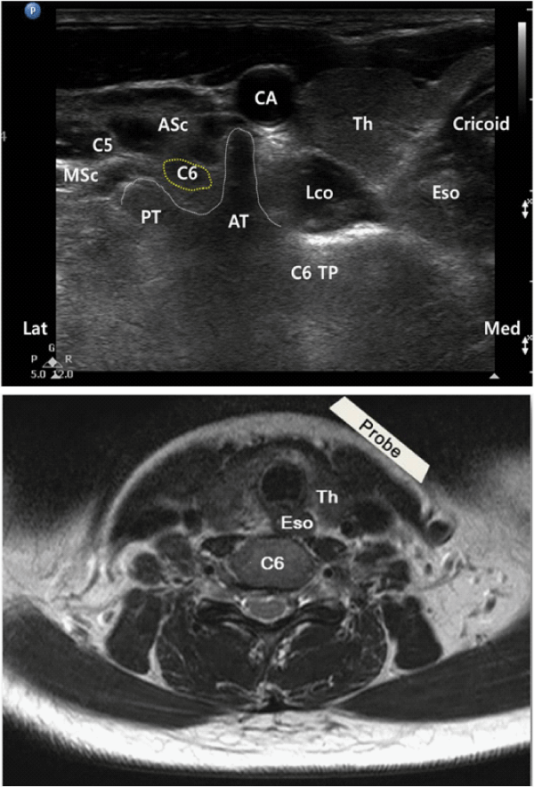
- The ultrasound probe is initially placed at the level of the cricoid cartilage, and the C6 transverse process (TP) is identified by the prominent anterior tubercle in the shortaxis view (Figure 1).The level of C6 is further confirmed by moving the US probe caudally to reveal the C7 TP with a single (posterior) tubercle. Subsequently, the consecutive cervical spine level is identified by moving the transducer cranially.
- Another way to determine the lower cervical spine level is by following the vertebral artery, which runs anteriorly at the C7 level before it enters the foramen of C6 TP in about 94% of cases. However, it enters at C5 or higher in the remaining cases [7,10].
Figure 1: (A) Short-axis transverse US image showing the sharp anterior tubercle (AT) of the C6 TP (transverse process). C6 & C5 indicated each nerve root; CA, carotid artery; PT, posterior tubercle; Eso, esophagus; Th, thyroid gland; Lco, longus coli muscle; ASc, anterior scalene muscle; MSc, middle scalene muscle. (B) Cross-sectional MRI image related to the transverse US image.
Upper cervical spine procedures
- Long-axis view: The ultrasound probe is applied over the midline to obtain a long-axis view of the spine. The occiput, C1 (no or rudimentary spinous process, SP), and C2 can be easily identified.
- Short-axis view: First, the occipital bone is identified, and by moving the transducer slowly caudal, the C1 arch is identified, and subsequently the first bifid SP belongs to C2. Once the C2 SP has been found, the transducer is moved laterally to visualize the lamina first and then, more laterally the articular pillar of C2. Moving the transducer only 1-3 mm more caudally, the vertebral artery appears and by following this artery caudally, the vertebral artery disappears in the transverse foramen of C2, and the C2-3 joint appears posteriorly. From this position, consecutive articular pillars can be identified by moving the transducer caudally.
US-guided Cervical Medial Branch Block (C-MBB) using the Short-axis or Long-axis view [1]
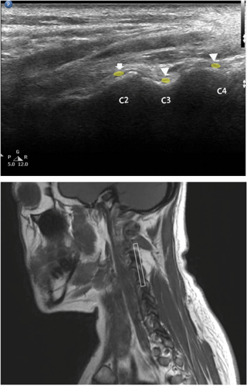
- The long-axis view for C-MBB minimizes the risk of miscounting the cervical level, can be better identified the nerves as an oval structure, and is appropriate for radiofrequency ablation of the medial nerves (Figure 2).
- The short-axis view offers better visualization of critical blood vessels as they course anteriorly across the articular pillar in toward the neuroforamen [11,12].
Narouze recommends performing a preinjection scan in the short-axis view to identify any blood vessels near the target area, after which the needle can be placed in the same view to avoid these blood vessels. Then, a long-axis view should be obtained to identify the actual medial branches; the needle can be adjusted slightly as needed [1].
Figure 2: (A) Sagittal (longitudinal) US view at C2-3 level showing the third occipital nerve (arrow) crossing C2-3 joint and the C3 & C4 medial branches (arrowheads) at the deepest point (waist) of the articular pillar. (B) Sagittal MRI image related to the longitudinal US image at C2-3 level. A gray rectangle is a footprint of US probe.
US-guided Cervical Selective Nerve Root Block [7]
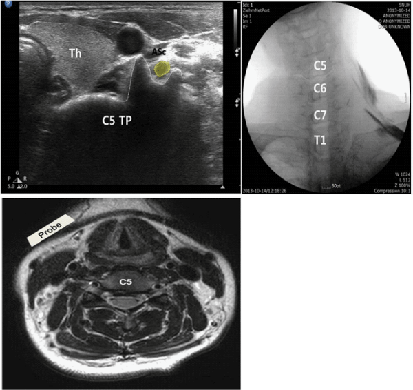
We can easily identify the cervical TP with the anterior and posterior tubercles as hyperechoic structures presenting "2-humped camel" sign and the hypoechoic round-to-oval nerve root in between [7]. The C6 TP shows much sharper anterior tubercle than those of TPs in upper cervical spine levels. First, the cervical level is determined by identifying the TP of the 7th and 6th cervical vertebrae. Then, by moving the transducer cranially, the appropriate spinal level is identified, a 22-guage blunt-tip needle can be introduced underreal-time US guidance from posterior to anterior with an in-plane technique to target the corresponding cervical nerve root (from C3 to C8) at the external foraminal opening between the anterior and osterior tubercles of the TP. One can successfully monitor the pread of the injectate around the cervical nerve with real-time US, and the absence of such spread around the nerve root may suggest unsuspected or unintentional IV injection.
It's quite difficult to monitor the spread the injectate through the foramen into the epidural space because of the bony dropout artifactof the TP. Therefore, this procedure would be referred to as a "cervical selective nerve root block" rather than cervical transforaminal epidural injection (Figure 3).
Although visualization of nerve root, soft tissues, vessels, and the spread of the injectate around the nerve, many pain physicians believe that visualization of very small vessels (radicular arteries) may be very challenging and thus real-time fluoroscopy with contrast injection and digital subtraction (when available) should remain the standard of care.
Figure 3: (A) Short-axis transverse US image showing the anterior and posterior tubercles of the C5 TP (transverse process) as the "2-humped camel" sign and fluoroscopic image showing after C5 & C6 selective nerve root after their root blocks using US. ASc indicates anterior scalene muscle; Th, thyroid gland. (B) Cross-sectional MRI image related to the transverse US image.
What about the Phrenic Nerve?
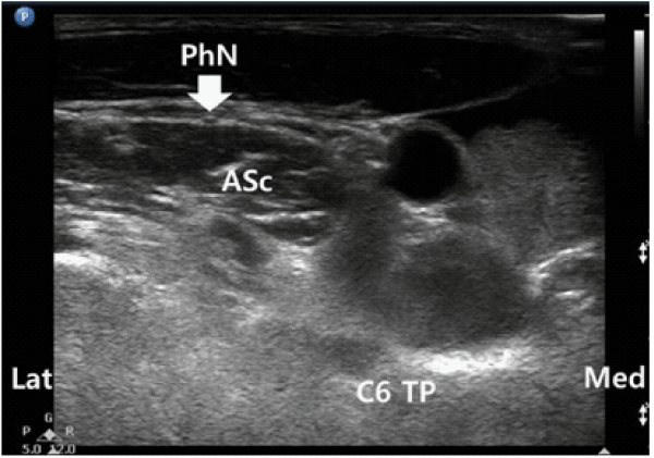
The phrenic nerve is a small (< 1 mm in diameter), monofascicular nerve that arises from the third, fourth, and fifth cervical ventral rami. The most consistent contribution is from the 4th cervical ventral ramus. At the level of the cricoid cartilage, the phrenic nerve is essentially coincident with the C5 ventral ramus [13]. As the nerve descends the neck, it travels from lateral to medial over the surface of the anteriorscalene muscle (Figure 4). If you seek to identify the phrenic nerve, perform the trace back maneuver and look for a hypoechoic oval structure moving across the anterior scalene muscle. During trace back (from caudad to cephalad) the phrenic nerve runs from the medial to lateral aspect of the anterior scalene muscle and receivescontributions from the C4 and C5 nerve roots. The nerve usually enters the chest between the subclavian artery and vein. Accessory phrenic nerves are observed in 60% of specimens and often derive from the 5th cervical ventral ramus [14].
Phrenic nerve imaging is important for two reasons. First, it may be possible to reduce the incidence of transient pulmonary complications related to phrenic nerve block using ultrasound. Diaphragmatic aresis or palsy is noted in 100% of the patients following a cervical plexus block. Most patients can tolerate diaphragmatic paresis or palsy without clinical symptoms. Ultrasound guidance allows more caudal approaches to brachial plexus block with an even lower chance of phrenic nerve block. However, the following is a list of absolute or relative contraindications of a Cervical Plexus Block: contralateral diaphragmatic paresis, morbid obesity, partial respiratory failure, regardless of cause, non-cooperative patients.
Second, direct trauma to the phrenic nerve can potentially be avoided during interventional procedures (stellate ganglion block with in-plane lateral approach or interscalene brachial plexus block) in the cervical region. Additionally, the use of US guidance with nerve stimulation has been reported for the performance of phrenic nerve block in a case of refractory hiccup and could avoid potential direct nerve injury during pain procedures [15].
Figure 4: Short-axis transverse US image at C6 vertebral level and phrenic nerve (PhN) anterior to the ASc (anterior scalene muscle). TP indicates transverse process.
Deep Cervical Plexus Block in Pain Management
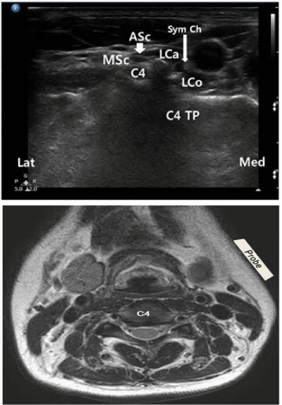
The scalene anterior was almost absent cranially above the C4 or C3 level in most cases. However, the longuscapitis became larger as it ascended above the C6 level. In the C4 vertebra, the scalene medius is attached not to the posterior tubercle but also to the anterior tubercle (Figure 5). The cervical plexus is situated in a groove between the longuscapitis and the scalenusmedius but not in the interscalene groove. The cervical sympathetic trunk is located on the anteromedial surface of the longuscapitis. Both are situated beneath the prevertebral fascia. According to the previous report by Usui, et al., when the contrast medium was confined to the longuscapitis, patients showed sensory block within cutaneous segments of the lesser occipital, the reater auricular, the transverse cervical, and the supraclavicular nerves and a relaxation of the ipsilateral neck muscles [6]. Ipsilateral ptosis, conjunctiva with warm sensation of the face, and nasal obstruction were also observed. These clinical effects suggest that injected anesthetic infiltrated into neighboring structures, which included the C2 to C5 roots and the sympathetic trunk.
Figure 5: (A) Short-axis transverse US image at C4 vertebral level. C4 indicated its nerve root; ASc, anterior scalene muscle; MSc, middle scalene muscle; C4 TP, transverse process; LCa, longuscapitis; LCo, longus coli; SymCh, sympathetic chain. (B) Cross-sectional MRI image related to the transverse US image.
Feasibility of US-guided Lateral AA Joint Injection [16]
The AA joint accounts for up to 16% of patients with occipital headache [17]. However, the clinical presentation of atlanto-axial joint pain is not specific and the only means of establishing a definite diagnosis is a diagnostic block with intra-articular injection of local anesthetic. There are three synovial joints between atlas and axis; laterally, paired joints between articulating facets and median joint between dens of axis anterior arch of atlas. We usually perform AA joint injection into its lateral joint using fluoroscope.
AA joint injections have the potential for serious complications; so it is imperative to be familiar with the anatomy of those joints in relation to the surrounding vascular and neural structures. The vertebral artery lies laterally to the AA joint as it courses through the C2 and C1 foramina. Then, it curves medially to go through the foramen magnum crossing the medial posterior aspect of the AO joint.
The C2 dorsal root ganglion (DRG) and nerve root with its surrounding dural sleeve cross the posterior aspect of the middle of the joint. Therefore, during AA joint injection, the needle should be directed toward the posterolateral aspect of the joint. This will avoid injury to the C2 nerve root medially or the vertebral artery laterally. Meticulous attention should be paid to avoid IV injection and inadvertent puncture of the C2 dural sleeve with cerebrospinal fluid leak or high spinal spread of the local anesthetics.
The C2 dorsal root ganglion (DRG) and nerve root with its surrounding dural sleeve cross the posterior aspect of the middle of the joint. Therefore, during AA joint injection, the needle should be directed toward the posterolateral aspect of the joint. This will avoid injury to the C2 nerve root medially or the vertebral artery laterally. Meticulous attention should be paid to avoid IV injection and inadvertent puncture of the C2 dural sleeve with cerebrospinal fluid leak or high spinal spread of the local anesthetics.
The procedure is performed with the patient in the prone position, using a high-frequency US transducer. A transverse short-axis view is obtained by applying the probe in the midline over the occiput and then scanning caudally to identify C1-2 level. C1 lacks a SP and the first bifid SP encountered is C2.
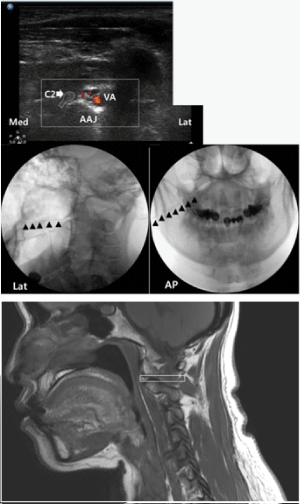
Then the probe is moved laterally until the C2 nerve root and DRG is seen, more laterally the AA joint appears in the image between the C2 DRG medially and the vertebral artery laterally (Figure 6). The probe is adjusted so that the AA joint is in the middle of the picture and a 22-gauge blunt-tip needle is advanced usually out-of-plane under real-time US guidance to target the AA joint just medial to the vertebral artery. The probe is then shifted to obtain a longitudinal scan at the C1-2 joint and the needle tip may need to be adjusted slightly to enter the joint cavity under vision.
Figure 6: (A) Short-axis sonogram with Doppler to show the vertebral artery (VA) just lateral to the atlanto-axial joint (AAJ) and fluoroscopic images showing after AAJ block using US. C2, C2 nerve root and dorsal root ganglion. (B) Sagittal MRI image related to the Short-axis US image at C1-2 level. A gray rectangle is a footprint of US probe.
Conclusion
There is no doubt that US has revolutionized the field of regional anesthesia in recent years, rapidly becoming the technique of choice in many pain centers in the world. There is inevitable urge to move on, from feasibility studies reporting the possible uses of US for pain blocks to outcome studies that support such an indication.
From this point of time, we would like to share a response from Helen Keller to the question, "Is there anything worse than being blind?" For those who are not familiar with Helen Keller, she not only overcame her blindness and deafness, among other disabilities, but became an inspiring social leader in America. To this question, she responded, "Yes. A person with sight but no vision". This is relevant to our topic-unless we have experience with sonoanatomy and trained the use of US for the performance of peripheral nerve blocks, axial blocks, and musculoskeletal injection, it may seem like you are working blind. We suggest it is high time to consider how to improve our knowledge of US-guided procedures, establishing recommendations for education and training, and encouraging clinical outcome studies.
References
- Narouze SN: Ultrasound-guided cervical spine injections: ultrasound "prevents" whereas contrast fluoroscopy "detects" intravascular injections. Reg Anesth Pain Med 2012, 37:127-130.
- Greher M, Kirchmair L, Enna B, Kovacs P, Gustorff B . Ultrasound-guided lumbar facet nerve block: accuracy of a new technique confirmed by computed tomography. Anesthesiology. 2004; 101: 1195-1200.
- Eichenberger U, Greher M, Kapral S, Marhofer P, Wiest R . Sonographic visualization and ultrasound-guided block of the third occipital nerve: prospective for a new method to diagnose C2-C3 zygapophysial joint pain. Anesthesiology. 2006; 104: 303-308.
- Narouze S, Vydyanathan A, Patel N . Ultrasound-guided stellate ganglion block successfully prevented esophageal puncture. Pain Physician. 2007; 10: 747-752.
- Narouze SN, Vydyanathan A, Kapural L, Sessler DI, Mekhail N . Ultrasound-guided cervical selective nerve root block: a fluoroscopy-controlled feasibility study. Reg Anesth Pain Med. 2009; 34: 343-348.
- Usui Y, Kobayashi T, Kakinuma H, Watanabe K, Kitajima T . An anatomical basis for blocking of the deep cervical plexus and cervical sympathetic tract using an ultrasound-guided technique. Anesth Analg. 2010; 110: 964-968.
- Narouze S, Peng PW . Ultrasound-guided interventional procedures in pain medicine: a review of anatomy, sonoanatomy, and procedures. Part II: axial structures. Reg Anesth Pain Med. 2010; 35: 386-396.
- Narouze SN . Ultrasound-guided cervical spine injections: time to put "outcome" before "income". Reg Anesth Pain Med. 2013; 38: 173-174.
- Narouze SN, Provenzano D, Peng P, Eichenberger U, Lee SC, et al. The American Society of Regional Anesthesia and Pain Medicine, the European Society of Regional Anaesthesia and Pain Therapy, and the Asian Australasian Federation of Pain Societies Joint Committee recommendations for education and training in ultrasound-guided interventional pain procedures. Reg Anesth Pain Med 2012, 37: 657-664.
- Bhatia A, Flamer D, Peng PW . Evaluation of sonoanatomy relevant to performing stellate ganglion blocks using anterior and lateral simulated approaches: an observational study. Can J Anaesth. 2012; 59: 1040-1047.
- Heckmann JG, Maihöfner C, Lanz S, Rauch C, Neundörfer B . Transient tetraplegia after cervical facet joint injection for chronic neck pain administered without imaging guidance. Clin Neurol Neurosurg. 2006; 108: 709-711.
- Edlow BL, Wainger BJ, Frosch MP, Copen WA, Rathmell JP, et al. Posterior circulation stroke after C1-C2 intraarticular facet steroid injection: evidence for diffuse microvascular injury. Anesthesiology 2010, 112: 1532-1535.
- Kessler J, Schafhalter-Zoppoth I, Gray AT . An ultrasound study of the phrenic nerve in the posterior cervical triangle: implications for the interscalene brachial plexus block. Reg Anesth Pain Med. 2008; 33: 545-550.
- Loukas M, Kinsella CR Jr, Louis RG Jr, Gandhi S, Curry B . Surgical anatomy of the accessory phrenic nerve. Ann Thorac Surg. 2006; 82: 1870-1875.
- Ojeda A, Sala-Blanch X, Moreno LA, Busquets C . Ultrasound-guided stellate ganglion block: what about the phrenic nerve? Reg Anesth Pain Med. 2013; 38: 170.
- Narouze SN, Casanova J, Mekhail N . The longitudinal effectiveness of lateral atlantoaxial intra-articular steroid injection in the treatment of cervicogenic headache. Pain Med. 2007; 8: 184-188.
- Aprill C, Axinn MJ, Bogduk N . Occipital headaches stemming from the lateral atlanto-axial (C1-2) joint. Cephalalgia. 2002; 22: 15-22.
