Review Article
Austin Chem Eng. 2023; 10(1): 1097.
Tank Jet Mixer Design, Arrangement & Applications
Laxmi Advani*
L&T Energy Hydrocarbon, India
*Corresponding author: Laxmi Advani L&T Energy Hydrocarbon, A M Naik Tower, Gate 3, 14th Floor, Jogeshwari - Vikhroli Link Road, Mumbai 400072, India. Tel: 9920875709 Email: Laxmi.thakker@gmail.com
Received: June 12, 2023 Accepted: July 11, 2023 Published: July 18, 2023
Abstract
Side entry mixers or jet mixers are commonly used to achieve mixing in storage tanks and reactors. Impellers are other conventional devices used for mixing in industry, but they are expensive for large storage tanks and underground tanks.
Jet mixers have been a better alternative to impellers in the process industry. Compared with Mechanically agitated mixers, these mixers use jet technique to create high turbulence, high shear rates and vortex motion offer several advantages in achieving rapid mixing over a short period of time without any moving parts. Jet mixing has become an alternative to conventional impeller mixing for various applications in process industries. To ensure optimal mixing performance, it is important to understand the basis of jet mixer design & also impact of different parameters in jet mixer design & preferred installation of mixers.
This article shall cover following aspects:
- Jet mixer Applications, working principle & Advantages
This section elaborates jet mixer applications in various industrial applications primarily in unit processes where liquid blending, solids suspension, flow generation or chemical reactions are key process parameters. It elaborates the working principle of jet mixer & lists its various advantages.
- Design aspects of jet mixers
This section includes defining turn over time, pumpage requirement, pump capacity & power determination which will help in design of jet mixer & connected assembly.
- Experimental correlations for Mixing time estimation based on literature with their limitations
Mixing time is an important design parameter in jet mixing. Various correlations are available in literature utilizing different parameters like jet velocity, jet diameter, tank height etc. to find out the correlation for mixing time. These have been defined based on experimental CFD analysis which will provide better conclusions for mixing time. Thus, critical analysis of the available literature data has been made and some general conclusions have been drawn concerning the various parameters.
- Impact of parameters affecting mixing time
This section highlights the impact of various parameters such as tank dimensions, jet mixer dimensions & geometry, fluid properties & mixer location & configuration details.
- Mixer installation guidelines
This section elaborates guidelines for mixer installation requirements, preferred position of mixers & multiple jets consideration.
- Quick comparison of jet mixer vs agitators
Fluids mixing can usually be achieved using mechanical mixers and jet mixers. Each of these mixers may be selected and used to provide optimal operative condition.
Keywords: Jet mixing; Mixing time; Experimental; CFD; Parameters; Design
Introduction
Fluids mixing can usually be achieved using mechanical mixers and jet mixers. Each of these mixers may be selected and used in order to provide optimal operative condition. However the jet mixing system is more effective than other mixing methods because they are very expensive for large storage tanks and underground tanks. Jet mixers are used in industrial applications primarily in unit processes where liquid blending, solids suspension, flow generation or chemical reactions are key process parameters. Mixing of reactants, catalysts etc. in a chemical and bio-chemical reactor can be achieved using a jet mixer, which offers the advantages of having no moving parts inside the reactor.
Working Principle
A liquid flow is taken from the tank and supplied to the liquid jet mixing nozzles via a pump. Inside the motive nozzle pressure energy is converted into kinetic energy. Negative pressure is generated at the motive nozzle outlet and the ambient liquid is sucked in.
The suction flow is strongly intermixed with the motive flow in the adjoining mixing section and accelerated by impulse exchange. The drag effect of the exiting mixed flow increases the mixing effect significantly.
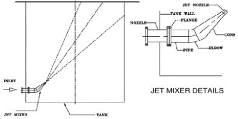
- Parts of Jet Mixer Assembly: Nozzle, Pipe, Elbow, Cone, Jet Nozzle (Below Figure 1)

Figure 1: Jet mixer Assembly.
Mixing nozzle is defined as plain pipe or tube where the pumped liquid is accelerated into the tank, as illustrated in Figure 2.

Figure 2: A jet nozzle can be as simple as a short length of reduced-diameter pipe where the circulating liquid is accelerated before discharging into the tank.
Jet mixers work best with Newtonian fluids with low (<0.01 Pa-s) viscosity. Viscous fluids require more invasive mixing for them to achieve a uniform consistency and jet mixers will probably not give satisfactory results.

Figure 3: Tank Mixing Eductors are used to agitate liquid, dissolve powdered solids in liquid, and to mix two or more liquids intimately within a tank or other vessel without the use of baffles or moving parts inside the tank.
Typical Arrangement
The jet is usually positioned near the bottom of a large storage tank, angled toward the opposite liquid surface as shown in figure 4 below:

Figure 4:
The length of the path from the nozzle to the tank wall should be as long as is practicable. This will incorporate more of the contents compared to a shorter path. For large storage tanks, jet mixers are usually installed near the bottom of the side wall and aimed at the far wall just below the liquid surface. This gives a diagonal path across the center of the tank. If the level drops below the target, however, the flow stream will hit the surface rather than the tank wall which reduces the mixing effectiveness.

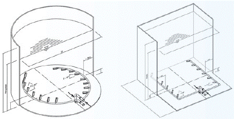
Figure 5: Shows an installation example in a tank & mixer arrangement in a neutralization basin.

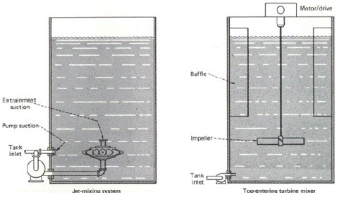
Figure 6: Shows a jet mixer and a top-entering turbine mixer in typical mixing vessels.
Small tanks (<4m diameter) can also be mixed with a jet mixer. The jet can be directed straight down if it is submerged and is not aimed at the tank outlet.
Advantages
Jet Mixers can be used as substitute for Agitators in practically all the cases where the liquids to be mixed are pumpable. Some typical applications of Jet Mixers are: Mixing / blending, Solid suspension, Electro coating / pretreatment tanks, Lube oil blending, Neutralization tanks, Storage tanks homogenization, Temperature Homogenization, Lube oil blending, etc.
Computational Fluid Dynamics (CFD)
To determine the optimum configuration of our tank mixing systems we perform Computational Fluid Dynamics (CFD) based on the specific frame conditions. This analysis enables to define the exact performance data as well as the best possible installation position to avoid any dead zones inside the tank. By using Computational Fluid Dynamics (CFD) it is possible to deliver perfectly designed tank mixing system, to decrease the energy input and to deliver clear installation instructions which enable a quick startup of the system.
Design of Mixers
Step 1: Determine required turn time. Turn time is the time required to turn the tank contents over once. For a jet mixer, the turn time is simply the liquid volume divided by the pumpage; pump age is typically five times the pump output, because of entrainment. The engineer estimates turn time based on the intensity of mixing required:
- For mild agitation, typically 3-60 min. Applications include dye-blending, neutralization, and storage-tank agitation.
- For medium agitation, typically 30 s-3 min. Applications include pH control and batch mixing (as well as solids suspension and heat transfer).
- For violent agitation, typically 10-30 s. Applications include flash mixing, disinfection and pigment blending (as well as gas/liquid contacting).
Detailed estimation for mixing time/turn time can be estimated using correlations in section 3.0.
Step 2: Calculate pumpage requirement.
Dividing the maximum liquid volume by the required turn time tells the required pumpage:
Pumpage = (Maximum volume)/(Turn time)
Step 3: Determine pump capacity, nominal pump horsepower and other parameters. Convert the pumpage to m3/min, then go to the table' and find the pumpage figure that equals or exceeds what is required. Then read in the same row the pump capacity, nominal pump horsepower, total primary nozzle area, number of primary nozzles, and area per nozzle. Note that the table assumes that pumpage is five times the pump capacity; this is based on 1-cP fluid viscosity, but is fairly accurate to 30 cP.
Step 4: Calculate actual motor horsepower
As for solids suspension, the nominal pump horsepower must be corrected for fluid specific gravity.
Experimental Correlations for Mixing Time Estimation based on Literature with Their Limitations
Mixing time is an important design parameter in jet mixing. Many experiments have been conducted in the literature to determine mixing time. In this section, various methods for mixing time determination and experimental correlations are explained in below table:
Impact of Parameters Affecting Mixing Time
Effect of tank height
From experimental correlations for mixing time, it can be observed that mixing time is directly proportional to tank height. So with increase in height of the tank, mixing time increases keeping other parameters constant.
Effect of tank diameter
It is observed that mixing time increases with increase in diameter of the tank and vice versa for constant set of other parameters.
Effect of jet velocity
From all correlations given in Table 1, it is observed that mixing time decreases with increase in velocity, and increases with decrease in velocity, when all other parameters are kept constant.

Table 1: Experimental correlations of jet mixing in tanks.
Effect of jet diameter
From most of the correlations it can be said that under same tank dimensions and jet velocity, mixing time is inversely proportional to jet diameter.
Effect of location of jet
Optimum nozzle depth ranges from the liquid surface level to three quarters of the liquid depth, when the liquid depth is equal to the tank diameter and is the mid depth of the liquid, when the liquid depth is smaller than the tank diameter.
Effect of jet angle
As per experimental reports, inclined jets at the bottom give better mixing times. It was found, that horizontal jets give larger mixing times than inclined jets at the bottom, and angle of 45 degrees gives reduced mixing times than angles of 30 degrees and 60 degrees.
Effect of jet configuration
Many experiments have been conducted with different configuration of jets such as inclined jets, vertical jets from the botFigure tom or top of the liquid surface, down ward pointing jet and upward pointing jet.
If the best configuration, which can eliminate poorly mixed regions, mixing time can be reduced to a greater extent.
Effect of Reynolds number
Experimental correlations depict mixing time is a strong function of Reynolds number, in the laminar regime and weak function in the turbulent regime.
So this fact i.e. ranges of Jet Reynolds number should be taken into consideration while designing jet mixer.
Effect of density (Stratification)
When the liquids to be mixed have comparable different densities or
Between the jet liquid and the bulk liquid and, if jet velocity is less than critical velocity, then layers of high and low density liquids form, and mixing will not occur in that situation. This is called stratification.
Effect of viscosity
Different fluids can have different viscosities. Viscosity can affect mixing time. The more viscous fluids have more difficulties for mixing. So change in viscosity is to be considered while calculating mixing time.
Limitations of this calculation:
The basic limitation of correlations presented in Table 1 is that they predict well only over the range of parameters i.e. correlations are case specific.
Available literature is concerned with liquid-liquid jet mixing and very few authors have considered solid sludge suspension using jet mixers.
Mixer Installation Guidelines
- The jet nozzle should always be submerged during the actual mixing operation.
- Side entry jets should be installed along a radius to the tank wall and should protrude no more than 5 dj from the tank wall. The nozzle should be no more than 5 dj from the tank floor or liquid surface. Axial jets should be installed perpendicular to and no more than 5 dj from the tank floor or liquid surface.
- CFD simulations could be extended to give proper choice of the position of the jet. Position of jet could also affect mixing time. This fact is to be taken into consideration in the design of jet mixing.
- The optimum angle of injection for mixers is 30°- 45° which will gives lower mixing times.
- Tank outlet location should not be near the jet location or else feed from the jet is taken directly entering into suction of the outlet system.
- Multiple jets:
Single axial jets only be used when the ratio of the tank height to diameter lies in the range of:
Single side entry jets should be used only when the ratio of the tank height to diameter lies in the range of:
Multiple side entry jets should be used only
Thus multiple jets should be used when designing a large diameter, shallow tank or a tall tank.
- O-ring set-up:
Jet mixers should be installed at the deepest possible point so that a good operation and an effective mixing is obtained even with a low liquid level. A level of 1–2 m above the jet mixer is sufficient to avoid foaming.
The required motive flow is supplied to the liquid jet mixing nozzles via these pipes. The motive flow pipes are situated oppositely to each other at two sides in the tank. Supply pipes can either be fixed on the tank wall or on the tank bottom. Pipe dimensioning will be according to normal flow velocities in order to keep the friction losses inside the pipes low. The size of each mixing nozzle, its alignment, e.g. the installation angle as well as the distance from one nozzle to another, are further results of the dimensioning.
For the evaluation of the number of mixers, following criteria are decisive which will be explained in subsequent sections:
Mixer geometry, size of the tank, basin liquid to be mixed, mixing time, maximal and minimal tank liquid level, etc.
Jet Mixers vs. Mechanical Agitators
Following comparison can be helpful in deciding mixers vs. mechanical agitators for applications:
Metal fatigue. The rotating parts in a mechanical agitator are subject to reversing stresses that cause metal fatigue and, often, failure of shafts, seals and agitator blades-especially in certain corrosion/temperature environments. A jet-mixing system is not subject to reversing stresses.
Mechanical components. A mechanical agitator has a shaft and gears, and may even have immersed bearings if the shaft is very long, but a jet mixer has no such parts. A jet-mixing system does have a centrifugal pump with a motor, while a mechanical agitator has just a motor. A mechanical-agitator system may have a feed pump, however.
Structural supports. A jet mixer is usually anchored to and supported from the bottom of the tank, but may be supported from the walls or top i (the tank is very deep. A top-entering agitator requires support at the top of the tank, which may mean specifying thicker walls or stronger materials.
Location in tank. A jet mixer is typically located about 0.5 m above the bottom of a tank, which saves energy in achieving off-bottom solids suspension because the mixing energy is provided where it is needed. A top-entering agitator typically requires about one impeller diameter of clearance at the bottom.
Manholes. A jet mixer may require a larger manhole in the top of the tank, because it may have a greater diameter than a typical mechanical agitator for the same application.
Liquid/ liquid blending. Experience show that a mechanical agitator requires about 25% less energy for blending liquids in tanks smaller than 3m dia. In larger tanks, jet mixers and mechanical agitators use about the same amount of energy.
References
- KL Wasewar. A Design of Jet Mixed Tank. Chem Biochem Eng Q. 2006; 20: 31–46.
- Zughbi HD, Rakib MA. Mixing in a fluid jet agitated tank: effect of jet angle and Elevation and number of Jets. Chem Eng Sci. 2004; 59: 829-842.
- Prakash R Bathija. Jet mixing design & Applications. Chemical Engineering. 1982.