
Research Article
Austin J Clin Case Rep. 2021; 8(7): 1219.
Intraoperative Spinal Cord Remote Monitoring with a Modified US A-Scope
Zaaroor M1, Sviri G2, Sinai A3, Constantinescu M4 and Halevy-Politch J5*
1Department of Neurosurgery, Rambam HCC and The School of Medicine at the Technion I.I.T, Haifa, Israel
2Department of Neurosurgery, Rambam HCC and The School of Medicine at the Technion I.I.T, Haifa, Israel
3Department of Biomedical Eng., with Specialization in Neurophysiology, Rambam HCC, Haifa, Israel
4Department of Neurosurgery, Rambam HCC, Haifa, Israel
5Department of Aerospace Eng., Technion I.I.T., Haifa, Israel
*Corresponding author: Jacob Halevy-Politch, Department of Aerospace Engineering, Technion I.I.T, Technion City, Haifa 32000, Israel
Received: May 20, 2021; Accepted: June 10, 2021; Published: June 17, 2021
Abstract
Materials and Methods: The motivation for this feasibility study were: (i) to modify the ultrasonic A-scope in order to monitor remotely, intraoperatively and in real-time tumor’s depth and size, before cutting its dura and to control tumor’s residual thickness while its resection and (ii) to demonstrate these abilities during several spinal-cord surgeries.
Results: The ultrasonic A-scope was modified for these purposes, to a noncontact, intraoperative and real-time device. It was successfully applied during several human spinal cord clinical trials. Its data were compared with those of a pre-operative MRI (of the same person), where a good similarity was obtained between them, with a difference less than 1mm, in most cases.
Conclusions: The modified A-Scope advantages: (i) remote, intraoperative and real-time monitoring; (ii) accurate and objective data was obtained; (iii) there is no direct contact between the US transducer and the monitored tissue, as the ultrasound propagates through a free stream of normal saline; (iv) the length of the free stream is few mm, at least; (v) the handpiece enables to monitor in a confined area, as it has a small foot-print; (vi) it is simple to operate the device; (vii) it enables to define intraoperatively tumor edges, before cutting and opening the dura.
Consequently, this modified device seems to be a valuable and useful tool to define intraoperatively tumor’s location and its complete removal and reducing potential damages to healthy tissues surrounding it.
Keywords: Ultrasound; Remote monitoring; Spinal-cord; Tumor
Introduction
The first application of the ultrasonic (US) A-scope (also named “US B-Scan”), was in Neurosurgery [1], for monitoring tumor-inbrain. Since the US Imaging System (IS) was developed, it replaced the US A-Scope that was not further developed. Although, the US IS are feasible, they have drawbacks, as: (i) are time consuming; (ii) provide suboptimal results [2,3]; (iii) the size of a US transducer limits its applicability in many neurosurgical cases [4] and also for tumor resection in confined areas. It is essential that in these cases, the residual tumor thickness should be monitored Intraoperatively (IO) and in Real-Time (RT). A good US conductivity is essential, which is solved by a thin layer of Normal Saline (NS) [5%, 25°C]). This thin layer of NS is produced by pouring the NS on the tissue to be monitored. A process that requires to stop the surgery; moreover, this solution is not feasible for confined areas. It was also recognized that specialization is essential [4] for a proper operation of an US IS and its image analysis; furthermore, some of these ISs are expensive [1,2,4,5].
A spinal cord surgery, is known as a sensitive and delicate one, with a high risk of post-surgical adverse effects [6-8]. These surgeries are planned, using data from images of a pre-operative Computer Tomography Image’s (CTI) and/or Magnetic Resonance Image’s (MRI) [9,10] and also from a Planar X-ray Image (PXI) (performed at the beginning of the surgery, when the patient is already anesthetized and in the ‘surgical position’). More information is obtained from neurophysiological intra-operative monitoring of spinal tracts [11-13], obtained by electrical stimulation of the motor cortex and recording responses of muscles, as known as (AKA) ‘Motor Evoked-Potentials’ (MEP’s) [14,15], or by stimulating the peripheral nerves and recording the subcortical and cortical responses, AKA ‘Somatosensory Evoked-Potentials’ (SEP’s). However, there is no IO device that provides data in RT and monitors it remotely.
A preliminary study using US was reported on newborns [7,8], for in-vitro studies, where a complete tumor resection was reported [16]. It was also applied during laminoplasty, as it is a useful method for evaluating spinal cord decompression status [12].
As known, CTI and MRI are applied during the pre-operative stages, for anatomic analysis and planning the surgery [9,15]. These IS are rarely used IO in the Operating Room (OR), and even then-they don’t provide the data in RT. Moreover, their price is much higher than the US IS and require dedicated trained personnel in the OR that measures and calculates the data from these images. Therefore, this data is “operator dependent” and subjective (‘operator’s decision’ where to start and stop the measurement on the image).
It will be shown here that the Improved US A-Scope (IUS) is the only true IO and RT monitoring device operating during a spinal cord surgery. IUS allows neurosurgeons to visualize and monitor soft tissue anatomic thicknesses instantly and continuously [6-8]. Although the conventional US ISs are simpler to operate compared to CTI and MRI, their quantitative information (data) is also not obtained in RT [6,7,16] and is also subjective.
Due to the following reasons the conventional US IS, used during tumor-in-brain neurosurgeries, are not suitable always for spinal cord surgery: (a) the size of an US transducer is too large in close vicinity to dura, or in a confined area; (b) the Active Surface (AS) of the US transducer and the examined tissue, should be in good US contact; (c) the size of the US transducer is too large for monitoring the residual tumor thickness during its resection; (d) it is not a RT measuring method, since time is required for processing [13], followed by a quantitative thicknesses evaluation; (e) the estimated error in depth (or thickness), as obtained for US IS, is in the range of 1.0 to 2.5 mm. (f) A thin layer of NS is required that prevents monitoring continuously. While resecting, these drawbacks may cause a damage to a healthy tissue in tumor’s vicinity. The motivation to overcome these drawbacks have led to improve the US A-Scope abilities by developing the IUS (Figure 1) that operates IO, in RT, remotely and provides simultaneously and objectively tumor’s depth, thickness and its residual thickness.
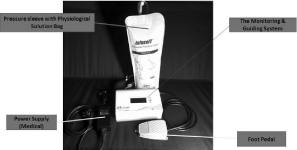
Figure 1: The IUS.
The IUS includes a pressurized sleeve with a replaceable bag of NS in it, a power supply and a foot pedal (to activate the system) operated by the neurosurgeon of the OR. The large display of the OR is connected to the IUS. Figure 2. Describes the handpiece. The IUS has a small footprint due to the tiny free stream (d=1.3 mm) of NS (originating at nozzle’s output and flows up to the monitored tissue’s surface). As US propagates through NS to the monitored tissue [17], there is no direct contact with the US transducer. The stream’s ‘free path’ (from the nozzle to the tissue) is usually few mm, and can be adapted to the surgery requirements; moreover, the stream can be directed in wide angular directions, enabling to monitor also in confined areas. Moreover, a small angular stream deviation, from perpendicular position to the surface, does not influence the resultant data.
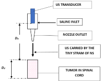
Figure 2: The front-end (handpiece) of the IUS.
Materials and Methods
The measuring principle of IUS is described in Figure 2 and the handpiece - in Figure 3, as modified for spinal cord surgery. The free-path NS stream is few mm from monitored tissue surface and orthogonal to it. The orthogonality can deviate about f = ±7°, as its influence is negligible on the measured results (as cos²f variations are small in this angular range). The detected signals are displayed simultaneously alpha-numerically and graphically - present the assessed thicknesses. This measurement is of an objective nature, since during signals collection and their processing, there is no human intervention.
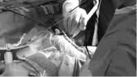
Figure 3: The IUS handpiece, as applied during a spinal-cord neurosurgery.
During a surgery, the neurosurgeon holds the handpiece and directs the stream toward the tissue surface. US propagation is described in [17] for a similar case.
The time difference between two consecutive signals defines the ‘propagation time’ and by knowing the propagation velocity in that tissue, its thickness is assessed.
Notes: Recent version of the IUS was applied successfully during tumor-in- brain clinical trials [22] and previously in orthopedics [13] and Dental Implantation Surgeries (DIS) [11,17-19].
When IUS was applied in a spinal cord surgery, the following data was obtained IO, in RT and simultaneously: (a) tumor size and thickness; (b) tumor’s residual thickness (during its resection) and (c) spinal cord morphology - while IUS scans along (and above) the dura. These properties of IUS provide a better understanding and ability to judge patient’s condition; thus, gaining more confidence, followed by a better outcome.
The IUS (Figure 1) comprises of three major sub-units: (1) a display (Figure 4) - graphical and an alpha numeric data of measured paths: (tumor depth, its thickness at the location of measurement and during resection its residual thickness is presented); (2) electronics (part of Figure 1) includes: a transmitter (Tr), a Transmit-Receive (Tr/Rc) switch, a receiver (comprised of a Low-Noise Amplifier (LNA), an Analog-to-Digital Converter (ADC) and a Digital Signal Processor (DSP) circuitry and software). IUS includes also a memory - for storing the measured data, used for comparisons and further analysis; (3) the ‘front-end’ (the ‘handpiece’ (Figure 3), as applied during a spinal cord surgery. A train of US pulses are emitted by the US transducer, continue to the nozzle and propagate through the tiny stream - up to the investigated tissue. Part of the reflected pulses reach the same US transducer that detect and transform them to electrical signals and by coherent integration [20,21] - their Signal-to-Noise Ratio (SNR) was improved.
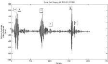
    Figure 4: Example of IO US backscattered signals, obtained on the
display of IUS. The abscissa represents distance (thickness) in samples (1
sample = 0.15 mm) and the ordinate - relative reflections (%). It describes
the morphologic cross-section of the spinal cord: A-B and D-E are dura
thicknesses, close to the handpiece outlet (nozzle) (Figure 2) and far from
it, respectively; B-C is the spacing between inner side of the dura and the
spinal cord; C-C’ is the spinal cord diameter (thickness); B-D is the spinal
cord canal diameter.
Results
Depths and thicknesses data of intradural-extramedullary tumor were compared, using the IUS and a pre-operative MRI (Figure 5).
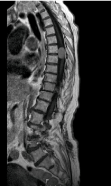
    Figure 5: A sagittal MRI image of an intradural-extramedullary tumor in a
spinal cord of a patient that participated in this clinical trial.
This clinical study was performed after obtaining approvals from the Helsinki committee of the hospital and the Ministry of Health. The clinical trials were performed on three patients (2 man in the age of 45 and 52 and a woman at the age of 58), after receiving their consents in writing. The tumor location was similar in all three cases.
While the IUS was applied IO in a spinal cord surgery, the neurosurgeon obtained in RT and simultaneously morphologic data (Figure 4): (a) dura thickness, (b) spacing between the inner dura wall and the spinal cord and (c) diameter of the spinal cord.
In a different mode of IUS, its handpiece was moved above dura - providing spatial tumor location, including its length and local thickness - critical during these surgeries, to define the location to cut the dura. The local thickness variations, obtained from reflected signals (Figure 6), relate to tumor’s length and thickness, where this data is obtained during a neurosurgery, before the dura was cut and opened.
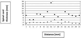
    Figure 6: Spinal cord thickness variation [mm], assessed IO along its
dura, measured with the IUS. Squares represent dura’s total thickness and
diamonds – those of spinal cord thickness. The abscissa (X-axis) represents
the measured location with the IOS handpiece (it was displaced along and
above dura’s spinal cord), and the ordinate (Y-axis) represent the assessed
thicknesses (mm).
Table 1 describes the measured data of a spinal cord, assessed from a pre-operative MRI and the IO IUS. Tumor’s size and depth were obtained solely by the IUS, while sliding its handpiece along and above dura’s spinal cord.
Measurement
Dura
ThicknessTumor
ThicknessTotal
Spinal cord
DiameterSpinal cord
Canal
DiameterType
No.
mm
mm
mm
mm
MRI
1
1.3
10.5
3.5
5.9
5.8, above tumor2
1.3
13.8
5.3
14.2, on tumor
3.8, above tumor3
0, at the tumor
1, out of tumor9.5
10.5, below tumor
5.6, above tumor5.6, below tumor
6.6, above tumorIUS
1
1.4
9.8
2.9
6.2
2
1.1
13.1
4.8
15.9
3
1.3
10.2
5.8
4.9
Table 1: Data from IUS and MRI.
Conclusion
The IUS was applied successfully (IO, in RT and remotely) during neurosurgeries of intradural-extramedullary tumor in human spinal cord. The data obtained with IUS were in good agreement with those of a pre-operative MRI: (a) almost identical dura thicknesses, with a difference of 0.1 mm. (b) the difference in tumor thickness was not larger than 0.7 mm; (c) the differences in spinal cord diameter, were not larger than 0.6 mm. (in one case, probably it measured also below the tumor and therefore provided larger difference); (d) the differences in spinal cord canal diameters, were not larger than 1.7 mm, probably due to differences in the locations of measurement.
The IUS proved itself during these clinical trials, as a non-contact method with a small footprint. IUS ability to monitor IO tumor edges in the pre-cutting stage, helps to define better tumor’s location.
Notes: (a) IUS has a useful application during laminoplasty, for evaluating spinal cord decompression status. The original classification, based on restoration patterns of the space ventral to the spinal cord, is considered to be practical for predicting neurologic improvement in cervical compressive myelopathy. (b) Mini-invasive approach such as hemilaminectomy has been widely introduced clinically to remove extra-medial tumors. Since IUS monitors remotely and on a small area (1.3 mm in diameter), we found this kind of ‘probe’ suitable also in these cases.
As this feasibility study was successful, but with a limited number of clinical trials, it is suggested to continue it with a larger population that will include different types of tumors and their locations. Considering positive results of this study, the IUS will be valuable and useful for locating tumor followed by IO monitoring till its complete resection, which will reduce damage to the surrounding healthy tissues and also time of the surgery.
References
- Galicich JH, Lombroso CT, Matson DD. Ultrasonic B-scanning of the brain. J Neurosurg. 1965.
- Lindseth F, Lango T, Bang J, Nagelhus HTA. Accuracy evaluation of a 3D ultrasound-based neuronavigation system. Comput Aided Surg. 2002; 7: 197–222.
- Lindseth F. Ultrasound Guided Surgery, Norwegian University of Science and Technology. 2002; 82-471-5538-5539.
- Mahboob S, McPhillips R, Qiu Z, Jiang Y, Meggs C, Schiavone G, et al. Intraoperative ultrasound guided resection of gliomas: a meta-analysis and review of the literature. World Neurosurg. 2006; 92: 255–263.
- Unsgaard G, Rygh OM, Selbekk T, Muller TB, Kolstad F, Lindseth F, et al. Intra-operative 3D ultrasound in neurosurgery. Acta Neurochir. 2006;148: 235–253.
- Prada F, Vetrano IG, Filippini A, Perin MDBA, Casali C, Legnani F, et al. Intraoperative ultrasound in spinal tumor surgery. J Ultrasound. 2014; 17: 195-202.
- Vasudeva VS, Abd-El-Barr M, Pompeu YA, Karhade A, Michael W, Groff MW, et al. Use of intraoperative ultrasound during spinal surgery. Global Spine J. 2017; 7: 648-656.
- Zhou H, Miller D, Schulte DM, Benes L, Bozinov O, Sure U, et al. Intraoperative ultrasound assistance in treatment of intradural spinal tumors. Clin Neurol Neurosurg. 2011;113: 531-537.
- Sherman JL, Nassaux PY, Citrin CM. Measurements of the normal cervical spinal cord on MR imaging. Am Neuroradiol; J 1990; 11: 369-372.
- Unsinn KM, Geley T, Freund MC, Gassner I. US of the Spinal Cord in Newborns: Spectrum of Normal Findings. Variants, Congenital Anomalies and Acquired Diseases, Radiographics. 2000; 20: 923-938.
- Machtei EE, Zigdon H, Levin L, Peled M. Novel Ultrasonic Device to Measure the Distance from the Bottom of the Osteotome to Various Anatomic Landmarks. J Periodontology. 2010; 81: 1051-1055.
- Mihara H, Kondo S, Takeguchi H, Kohno M, Hachiya M. Spinal cord morphology and dynamics during cervical laminoplasty: evaluation with intraoperative sonography. Spine. 2007; 1: 2306-2309.
- Rosenberg N, Halevy-Politch J. Intraosseous monitoring of drilling in lumbar vertebrae by ultrasound: an experimental feasibility study. PLOS ONE. 2017; 1-9.
- Epstein NE, Surg. The need to add motor evoked potential monitoring to somatosensory and electromyographic monitoring in cervical spine surgery. Neurol Int. 2013; 29: S383-S391.
- Feng B, Qiu G, Shen J, Zhang J, Tian Y, Li S, et al. Impact of multimodal Intraoperative monitoring during surgery for spine deformity and potential risk factors for neurological monitoring changes. J Spinal Disorder Tech. 2012; 25: 108-114.
- Van Eerd M, Patijn J, Sieben JM, Sommer M, van Zundert J, Van Kleef M, et al. Ultrasonography of the cervical spine: an in vitro anatomical validation model. Anesthesiology. 2014; 120: 86-96.
- Rusnak I. Halevy-Politch J. Rosenberg N. Trabecular bone attenuation and velocity assess by ultrasound pulse-echoes. Appl. Acoustics. 2020; 157: 1-8.
- Zigdon-Giladi H, Saminsky M, Elimelech R, Machtei EE. Intraoperative measurement of the distance from the bottom of osteotomy to the mandibular canal using a novel ultrasonic device. Clinical Implant Dentistry and Related Research. 2016; 18: 1034-1041.
- Rosenberg N, Craft A, Halevy-Politch J. Intraosseous monitoring and guiding by ultrasound: A feasibility study, Ultrasonics. 2014; 54: 710–719.
- Gatit P, Jacob D. Coherent integration efficiency diversity and detectivity of temporally integrated random coherent LADAR signals. Proc. SPIE7684. 2010.
- Miller K. An analysis of coherent integration and its application to signal Detection. IRE Trans. On Information Theory. 1957; 3: 214-219.
- Halevy-Politch J, Zaaroor M, Sinai A, Constantinescu M. New US device versus imaging US to assess tumor-in-brain, Chinese Neurosurgical Journal. 2020; 6: 28.