
Special Article – Dental Implants
J Dent App. 2016; 3(3): 340-346.
Investigation of Biomechanical Aspects of the Screw- Retained Restoration Secured by Conical Head Abutment Screw: A Finite Element and Mathematical Analysis
Taghavi H¹, Arabi Z², Rahmani Z³, Alikhasi M4, Bulaqi HA5, Paknejad M6 and Safari H7*
¹Department of Prosthodontics, School of Dentistry, Qom University of Medical Sciences, Qom, Iran
²Department of Computer Engineering, Payame Noor University, Tehran, Iran
³Oral and Maxillofacial Research Center, Dentistry Faculty of Tabriz University of Medical Sciences, Tabriz, Iran
4Department of Prosthodontics, Faculty of Dentistry, Tehran University of Medical Sciences, Tehran, Iran
5Department of Mechanical Engineering, School of Mechanics, University of Tehran, Tehran, Iran
6Department of Periodontics, School of Dentistry, Tehran University of Medical Sciences, Tehran, Iran
7Department of Periodontics, School of Dentistry, Qom University of Medical Sciences, Qom, Iran
*Corresponding author: Hamed Safari, Department of Periodontics, School of Dentistry, Qom University of Medical Sciences, Qom, Iran
Received: October 18, 2016; Accepted: November 16, 2016; Published: November 18, 2016
Abstract
Introduction: The purpose of this study was to investigate the biomechanical aspects of screw-retained restorations secured by conical-head abutment screws.
Materials and Methods: A Three-dimensional finite element models of a Straumann implant, a cast-to gold abutment, a conical-head abutment screw, and prostheses with screw-retained fixation method were constructed. ABAQUS software was used to simulate the one-step process of screw tightening. Additionally, to separately recognize the behavior of each influential parameter, mathematical method was used to reduce the computational costs. Distribution of stress and radial displacement obtained by FE analysis were presented, and predicted values of the stresses in cross-sectional areas of the prostheses, obtained by mathematical method, were presented in regard to influential parameters (ceramic thickness and cone angle of conical-head abutment screw).
Results: During tightening, due to the conical nature of the abutment screw, lateral pressure was developed in the internal conical region of abutment, and thus caused stresses within and around the prostheses. The distribution of tangential stress along the Metal-Ceramic thickness was not uniform. Cone angle of conical head abutment screw (up to 30 degrees) has a reverse effect on stresses created in the metal-ceramic interface, in contrast to the ceramic thickness.
Conclusion: Metal ceramic interface bonding acts as a stress concentration point in screw-retained restorations due to the differences in material properties. In the cross-sectional areas of the prostheses, lateral pressure arising from conical-head abutment screw tightening can propagate the existing microcracks in metal-ceramic interface and thus can lead to porcelain fracture or chipping of the veneer.
Keywords: Conical-Head Abutment Screw; Screw-Retained Restoration; Metal-Ceramic; Finite Element Analysis; Mathematical Analysis
Introduction
Implant-supported restorations either cement retained or screwretained, are a common treatment modality for missing teeth [1-5]. Although both retention types have advantages and disadvantage [1- 6], the choice of connection type is based on the clinician’s preference [4,7]. According to various studies, while screw-retained restorations offer retrievability, higher stability and security [8,9], cement-retained restorations have the potential for complete passivity as their primary advantage [3,10,11].
Considering implant survival and failure rates, there are no significant differences between screw- and cement-retained restorations [1,2,12,13]. In a systematic review, the estimated 5-year restoration survival rate was 96.03% for screw-retained restorations and 95.55% for cement-retained restorations [1]. However, some authors reported statistically significant differences in technical and biologic complications between screw- and cement-retained restorations [1,2,13]. Sailer et al [13], indicated that technical complications occurred primarily with screw-retained restorations and that biologic complications occurred primarily with cementretained restorations.
Some investigators reported that porcelain fracture or chipping of the veneer in implant-supported restorations was more prevalent in screw-retained restorations than cement-retained restorations, as a technical complication [1,2,14-16]. In an in-vitro study performed by Torrado et al [14], the fracture resistance of porcelain was demonstrated to be significantly higher in cement-retained restorations than in screw-retained restorations. In another in-vitro study, Karl et al [15], indicated that weak points in the ceramic layer are caused by the presence of screw-access holes in screw-retained restorations. Nissan et al [16], observed that the incidence of porcelain fracture was 38% for screw-retained restorations and 4% for cementretained restorations.
Screw-retained restoration could be directly connected to the implant using cast-to or castable abutments. The design of the abutment-abutment screw head interface can be either conical-head or flat-head [17]. Conical-head joints provide increased stability and seal performance due to a friction-locking mechanism between the two mating parts [17,18]. Coppede et al [17], concluded that the shape of the abutment screw head significantly affected the resistance to screw loosening. Budynas and Nisbett presented a lateral pressure on the conical region under axial force (preload) [19]. This pressure leads to the generation of radial stress in the cross-section of the conical region. In a systematic review, Wittneben et al [1], reported that the existence of radial stress may interrupt the integrity of the metal frame and the porcelain veneer at their interface during tightening of the assembly.
The application of metal-ceramic (MC) restorations is common in prosthetic treatment [20]. Several previous studies discussed the causes of porcelain fracture in the context of MC restoration failures [21-23]. Although, the ceramic materials used in MC restorations have the advantages of high biocompatibility and esthetic, the primary disadvantage of these materials is sensitivity to microscopic cracks due to their brittle nature [24]. Furthermore, cracks can be created during the process of fusing and cooling porcelain on the metal frame due to differences in bulk modulus and thermal coefficient of expansion between the materials [23,25].
Porcelain fracture and delamination of metal-ceramic bonding have been implicitly reported based on clinical and experimental comparative studies of screw- and cement-retained restorations. A comprehensive study of the reason causing this phenomena has not been conducted. Moreover, few studies have considered the reason why screw retained-restorations have low fracture resistance.
This gap in the literature may be caused by the restrictions of the conventional experimental methods. However, the finite element method facilitates an accurate study of the stress and strain distribution within the models by overcoming the problems of the conventional methods such as stress measuring within the models and time consuming.
Therefore, the aim of this study was to investigate the biomechanical aspects of the technical problems such as porcelain fracture or chipping of the veneer associated with screw-retained restorations secured by conical-head abutment screws, and also the reason of high possibility of their fracture.
Materials and Methods
Finite element modeling
The primary form of the second premolar tooth was used for computer-aided design (CAD) modeling of the implant-supported single restoration with screw-retained fixation method. In the CAD model, the metal frame and the porcelain were modeled on the abutment to ensure that they acted as one piece, and the abutment hole was continued to the occlusal surface to provide accessibility to the abutment screw and the ability to tighten the screw. Additionally, lingual ledge for the metal framework was considered. The threedimensional CAD model of the screw-retained restoration is presented in Figure 1A.
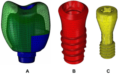
    Figure 1:  Three dimensional of FEM models. (A) Screw-retained restoration,
(B) Implant, (C) Abutment screw.
The exact geometries and dimensions of a 4.1×8 mm Straumann implant (SLA 043.031S; Institute Straumann), a directly attached abutment (048.642; RN SynOcta gold abutment), and an abutment screw (048.356; SynOcta basal screw) were obtained through microscope projection. The CAD models were constructed using the SOLIDWORKS software (DassaultSystèmes). To simulate the screw tightening process and create a secure preload within the implant complex, the outer surface of the abutment screw was geometrically modeled with a continuous spiral threaded helix, and the inner surface of the implant was geometrically modeled with a continuous spiral threaded bore (Figure1B and1C). After assembling the implant complex together with the screw-retained restoration, the initial position of the abutment screw within the implant complex was modeled as “snug tight”.
To perform a dynamic simulation of the screw tightening process, the CAD models were transformed into the ABAQUS 6.11 software (DassaultSystèmesSimulia Corp). An explicit dynamic simulation was performed in one step, with the abutment screw turned enough to achieve the target torque of 35Ncm (according to the manufacturer’s recommendations). Explicit dynamics analysis is computationally efficient for the analysis of large models with relatively short dynamic response times and for the analysis of extremely discontinuous events or assembly processes, and also allows for the definition of very general contact conditions.
The contact interfaces and tangential behavior of the reciprocal interfacing surfaces were considered. The coefficient of friction at the contact interfaces of the abutment screw, the abutment and the implant was considered to be equal to 0.12 [26,27]. The metal frame-porcelain contact interface was defined as “tie”. Additionally, a boundary condition was applied to the external surface of the implant. The explicit element library with linear geometric order was used to generate the tetrahedral elements. Table 1 lists the number of elements for each part. All materials were considered to be isotropic and homogeneous. The mechanical properties of the materials are presented in Table 2 [28].
    Part
    No. of Elements


    Implant
    76894


    Abutment screw
    27238


    Porcelain
    29229


    Abutment + metal frame
    25961
Table 1: Number of tetrahedral elements for each part.
    Material component
    Young’s modulus (GPa)
    Poisson’s ratio
    Density
      Density(g/cm3)
    Strength
      (MPa)
    Elongation    (%)


    Gold abutment+metal frame*
      136
      0.37
      17.5
      765
      10 min


    Titanium grade 4*
      110
      0.34
      4.5
      550
      15 min


    Porcelain [28]
    68.9
    0.28
    2.44
    145
    2 max


    *According to the manufacturer’s    specifications.
Table 2: Mechanical properties of materials.
Mathematical modeling
In order to perform the mathematical analysis, all related equations were extracted. The relationship between the preload F and the torque applied in the abutment screw Tw can be described as follows [19]:
Where Tc represents the conical torque in the conical region of the abutment screw according to the uniform wear theory, Tth represents the thread torque in the threads region of the abutment screw, μ is the coefficient of friction in the threads and the conical head, d is the inner head friction diameter, D is the outer head friction diameter, β is the cone angle, a is the half angle of the thread, L is the thread pitch of the abutment screw, and dm is the pitch diameter (Figure 2).
According to the uniform wear theory for cone clutch [19], the maximum internal pressure Pa in the conical region of the abutment screw occurs in the inner head friction diameter d, and also the internal pressure Pi at the radius r1 that is shown at the cross section S-S in Figure 2 is given by:
Referring to Figure 2, for the two cylindrical parts under internal pressure Pi bonded by porcelain upon the metal frame, Budynas and Nisbett [19], presented (with the assumption that the longitudinal elongation is constant around the circumference of the cylinder) the tangential strain εθ, the tangential stress sθ, and the radial stress sr as:
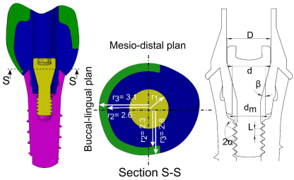
    Figure 2:  Cross-sectional view of 3D dimensional CAD models of screwretained
prosthetic. Metal frame and abutment (blue), Abutment screw
(yellow), porcelain (green), Implant (purple), (d=2.015 mm) (D=2.6 mm) (
a=2β= p/6 radian) (L=0.4 mm) (dm=1.66 mm).
Where the subscript m corresponds to the metal frame, the subscript p corresponds to the porcelain, r2 is the nominal radius of the contact between the metal and the porcelain or the internal radius of the porcelain, E is the elastic module, and ϑ is the Poisson ratio. Additionally, Pn is the nominal pressure that represents the pressure between the metal and the porcelain; this value can be obtained by solving the identical radial displacement ur=εθ×r at the contact region of the metal and the porcelain (r=r2).
ur,m=ur,p at r=r2 (10)
The distribution of stress and the radial displacement were presented for FE model of screw-retained restoration at buccal-lingual cross section. According to the predicted mathematical formulation (Eq. 1 to 10), the distribution of the stress and the radial displacement were evaluated along the metal-porcelain thickness (along buccallingual plan (r2=2.6 mm, r3=3.1 mm) and along mesio-distal plan (r2=2.3 mm, r3=2.8 mm). Additionally, the ratio of the porcelain to the metal frame thickness and the cone angle β were evaluated using the predicted equations to gain insight into the behavior of the parameters that influence the preload, the internal pressure in the conical region of the abutment screw, and the distribution and amounts of stress and radial displacement along the prosthesis thickness.
Result
Finite element results
Figures 3 and 4 shows the distribution of Von Mises stress and the radial displacement on the metal frame and on the ceramic of the screw-retained restoration at the target torque.
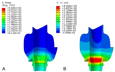
    Figure 3:  Distribution of Von Mises stress (A) and radial displacement, (B) in
metal frame and abutment.
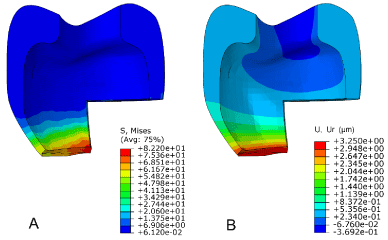
    Figure 4:  Distribution of Von Mises stress (A) and radial displacement, (B)
in porcelain.
Mathematical results
The predicted values of the tangential and radial stresses (Eq. 8 and 9) and the radial displacement (ur) along the metal-ceramic thickness at the cross section of screw-retained (r11=r=r3) are presented in Figure 5, and their values are presented in Table 3.
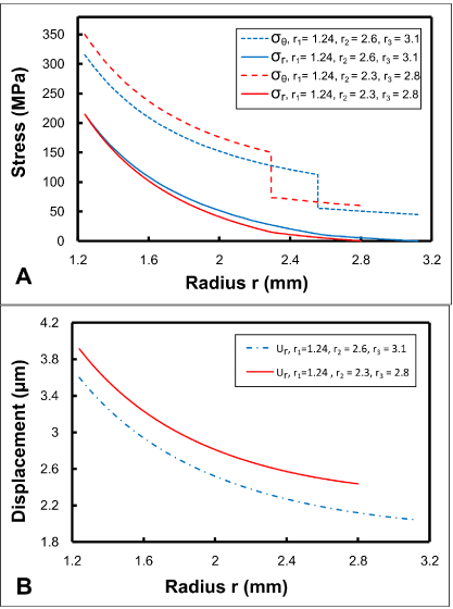
    Figure 5:  Distribution of stress (A) and displacement, (B) at path of metalceramic
thickness with different metal and porcelain thicknesses.
    sθ,m(MPa)
    sθ,p(MPa)
    sr(MPa)
    ur(μm)


    r=r2=2.6    mm &r3=3.1 mm
    112.7
    55.1
    10.0
    2.2


    r=r2=2.3    mm &r3=2.8 mm
    150.1
    73.2
    14.5
    2.6
Table 3: Stress and displacement values at outermost radius of metal.
The effect of the metal frame (r2-r1) and ceramic (r3-r2) thicknesses on the tangential (sθ) and radial (sr) stresses and the radial displacement (ur) in the contact region of metal ceramic (r=r2) are shown in Figure 6. The maximum values of the tangential and radial stresses (sθ,p=319.4 MPa & sr,p=214.6 MPa) and the radial displacement (ur=6.8 μm) occurred when the entire frame was ceramic (r2=r1). Additionally, the minimum values of the tangential and radial stresses (sθ,m=104.7 MPa & sr,m=0 MPa) and the radial displacement (ur=2.16 μm) occurred when the entire frame was metal (r2=r3).
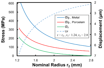
    Figure 6:  Stress and displacement in the contact region of metal ceramic as
a function of nominal radius r2.
Figure 7 shows the effect of the cone angle β of the abutment conical region on the created preload F and the internal pressure Pi and on the tangential and radial stresses and the radial displacement at the outermost radius of the metal frame. The values of these parameters at cone angles of 5, 15 and 30 degrees are presented in Table 4.
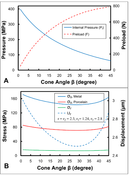
    Figure 7:  Internal pressure and preload (A), and stress and displacement at
r2=2.3 (B), as a function of cone angle.
    (r2=2.3    mm &r3=2.8 mm)
    Pi(MPa)
    F    (N)
    sθ,m(MPa)
    sθ,p(MPa)
    sr(MPa)
    ur(μm)


    β    = 1 degree
    329.6
    214.3
    171.6
    85.4
    16.6
    3.00


    β    = 15 degree
    214.6
    489.2
    149.6
    74.5
    14.5
    2.62


    β    = 30 degree
    117.6
    702.8
    143.0
    71.1
    13.8
    2.50
Table 4:  Values of internal pressure, preload, stress and displacement in
different cone angles.
Discussion
Finite element analysis is widely used in implant dentistry to understand nature of problems; this approach has some limitations compared to clinical studies [29]. For example, in clinical and real situation, the properties of materials are not to be isotropic and homogeneous that was assumed in finite element analysis. A physical understanding of the encountered problems, precise modeling techniques, and smooth surface meshing of the models to implement simulations that are closer to reality can increase the effectiveness of this method. To separately evaluate the influential parameters, mathematical methods are used to reduce the computational costs of finite element, because it is too time-consuming to create multiple finite element models of designs with various porcelain thicknesses and/or cone angles. It should be noted, the simulated (FE) results and predicted values (mathematical results) cannot be directly compared, because the nature of the results obtained from both methods are different. For example, finite element results, “Von Mises stress”, are as three dimensional and based on equivalent tensile stress, whereas mathematical results, “Plane Stress”, are as two dimensional and based on Hooke’s law [19]; however the indirect comparison of their results would be conceivable.
Porcelain fracture or chipping of the veneer and integrity interruptions or delamination of the metal-ceramic bonding is considered to be technical complications associated with implant restorations especially in screw-retained restorations [1,2,16]. Several studies [23-25], concluded that microcrack buds are created within ceramic at contact region of metal-ceramic during the process of fusing and cooling porcelain on the metal frame. These buds due to differences in bulk modulus and thermal coefficient of expansion between the materials [23-25]. These micro-cracks would start to propagate in the stress values much lower than the yield strength (Table 2). Figure 4A shows 82.2 MPa Von-Mises stresses for porcelain in the contact region with metal frame during screw tightening process. This amount of stress could result in residual stress within restorations. Regarding the brittle nature of porcelain, these stresses would lead to the metal-ceramic bonding delamination and propagation and growth of the existing microcracks.
Abutment screws with a conical-head design have exhibited superiority in terms of seal performance and the remaining torque in the conical regions [18]. To establish an appropriate preload and a stable abutment-implant connection, when the conical-head abutment screw is tightened by the wrench, the internal pressure is created in the internal radius of the abutment conical region due to the conical nature of the abutment screw [19]. This internal pressure develops both radial (sr) and tangential (sθ) stresses, with values that depend upon the radius and the cone angle of the conical region [19].
In this study, for the internal pressure created at the target torque, the maximum values of the radial displacement and stress occurred in the radius of r1 and gradually diminished along the thickness of the MC (Figures 3 and 5). According to the predicted values, the tangential stresses were greater than those of the radial stress (Figure 5A). In addition, in contrast to the radial stress, the distribution of the tangential stress along the MC thickness was not uniform; so in the contact region of the metal and ceramic (r=r2), the tangential stress of the metal was greater than that of the ceramic due to differences in elastic modulus. Hence, this difference between tangential stresses acts as a concentration stress at metal-ceramic interface.
Consequently can cause both delamination of the metal-ceramic bonding, and propagation and growth of the existing microcracks created during the process of fusing and cooling porcelain on the metal frame. These phenomena reduce the integrity of the metal and the ceramic bonding, which can ultimately cause an porcelain fracture during next functional stage (Figure 5) [1].
In practical situation, since the final prosthesis of a cementretained restoration is mounted on the abutment after tightening the abutment screw, these stresses and deformations have no effects on the final prosthesis and can be compensated by the passivity of the prosthesis [10,11]. In contrast, these stresses and deformations are transmitted to the ceramic layers in screw-retained restorations and can propagate existing microcracks, and delaminate metal ceramic bonding [24], ultimately leading to fracture or chipping within and around the ceramic (Figure 3) [1,23].
Ceramic thickness (r3-r2), with the same thickness of MC (r3- r1=1.56), has an direct effect on the stresses and radial displacements created within the contact region of the metal and ceramic; so that with decreasing the ceramic thickness (r3-r2), the tangential and radial stresses and the radial displacement decrease (Figure 6) [23]. Stress reduction in the metal-ceramic layers, through reducing ceramic thickness, can diminish integrity interruptions in screw-retained restorations [1,23]. On the other hand, despite advantages, such as high biocompatibility, aesthetics, and low plaque accumulation on ceramic materials, there are limitations associated with reducing the ceramic thickness [24].
With increases in the cone angle, the preload increases, as a parameter influencing the joint stability, whereas the internal pressure decreases, as a parameter influencing torque maintenance, seal performance, and screw loosening prevention (Figure 7A) [19]. It seems that the cone angle of 15 degrees is the breakeven point for the preload and internal pressure. This is the reason why most manufacturers choose an angle of 15 degrees for abutment conicalhead screw. According to the predicted values, the effect of the cone angle on the stress and radial displacement in the contact region of the metal and ceramic is reverse for cone angle values less than 30 degrees, and direct for cone angles greater than 30 degrees (Figure 7B). Thus, by increasing the angle from 1 to 30 degrees, the tangential stress and the radial displacement are decreased by 16.67% (Table 4). On the other hand, a limitation that is associated with increasing the cone angle and must be considered is the widening of the abutment screw access hole, which can compromise appearance and increase the probability of plaque accumulation [24]. In practice, clinicians are incapable of changing the cone angle and head design, but a precise recognition of the effect of each influential parameter can give them enough insight for the right choice of restoration and abutment connection types and abutment screw design among the various brands with different cone angles and head designs.
In this study, biomechanical aspects of a screw-retained restoration secured by abutment screw with a conical-head design were separately assessed to recognize the technical problems associated with porcelain fracture, and to determine the effect of each influential parameter. Although the results of this study cannot be directly confirmed in the clinic due to limitations in the experimental methods, they may pave the way to understanding of the effects of dynamic nature of screw-retained fixation method. However, it should be emphasized that screw-retained prosthesis that was designed in this study was considered completely passive. Lack of passivity could induce more stresses in the restoration and could justify porcelain chipping during screw tightening. Although the choice of cement- versus screwretained restorations is typically made based on clinician preference [4,7], accumulating evidence demonstrates that this choice can vary according to the connection type with different technical problems, and the functional conditions [6].
Conclusion
- Metal ceramic interface bonding acts as a stress concentration point in screw-retained restorations due to the differences in characteristics of the materials.
- In the cross-sectional areas of the prostheses, lateral pressure arising from conical-head abutment screw tightening can propagate the existing micro-cracks in metal-ceramic interface and thus can porcelain fracture or chipping of the veneer.
- Cone angle of conical head abutment screw (up to 30 degrees) has a reverse effect stresses created in the metal-ceramic interface, in contrast to the ceramic thickness.
- Wittneben JG, Millen C, Bragger U. Clinical performance of screw- versus cement-retained fixed implant-supported reconstructions-a systematic review. Int J Oral Maxillofac Implants. 2014; 29: 84-98.
- Sherif S, Susarla HK, Kapos T, Munoz D, Chang BM, Wright RF. A systematic review of screw- versus cement-retained implant-supported fixed restorations. Journal of prosthodontics: official journal of the American College of Prosthodontists. 2014; 23: 1-9.
- Taylor TD, Agar JR. Twenty years of progress in implant prosthodontics. J Prosthet Dent. 2002; 88: 89-95.
- Taylor TD, Agar JR, Vogiatzi T. Implant prosthodontics: current perspective and future directions. Int J Oral Maxillofac Implants. 2000; 15: 66-75.
- Jemt T, Linden B, Lekholm U. Failures and complications in 127 consecutively placed fixed partial prostheses supported by Branemark implants: from prosthetic treatment to first annual checkup. Int J Oral Maxillofac Implants. 1992; 7: 40-44.
- Silva GC, Cornacchia TM, de Magalhaes CS, Bueno AC, Moreira AN. Biomechanical evaluation of screw- and cement-retained implant-supported prostheses: a nonlinear finite element analysis. J Prosthet Dent. 2014; 112: 1479-1488.
- Vigolo P, Givani A, Majzoub Z, Cordioli G. Cemented versus screw-retained implant-supported single-tooth crowns: a 4-year prospective clinical study. Int J Oral Maxillofac Implants. 2004; 19: 260-265.
- Chee W, Felton DA, Johnson PF, Sullivan DY. Cemented versus screw-retained implant prostheses: which is better? Int J Oral Maxillofac Implants. 1999; 14: 137-141.
- Michalakis KX, Hirayama H, Garefis PD. Cement-retained versus screw-retained implant restorations: a critical review. Int J Oral Maxillofac Implants. 2003; 18: 719-728.
- Guichet DL, Caputo AA, Choi H, Sorensen JA. Passivity of fit and marginal opening in screw- or cement-retained implant fixed partial denture designs. Int J Oral Maxillofac Implants. 2000; 15: 239-246.
- Karl M, Taylor TD, Wichmann MG, Heckmann SM. In vivo stress behavior in cemented and screw-retained five-unit implant FPDs. Journal of prosthodontics: official journal of the American College of Prosthodontists. 2006; 15: 20-24.
- Weber HP, Sukotjo C. Does the type of implant prosthesis affect outcomes in the partially edentulous patient? Int J Oral Maxillofac Implants. 2007; 22: 140-172.
- Sailer I, Muhlemann S, Zwahlen M, Hammerle CH, Schneider D. Cemented and screw-retained implant reconstructions: a systematic review of the survival and complication rates. Clin Oral Implants Res. 2012; 23: 163-201.
- Torrado E, Ercoli C, Al Mardini M, Graser GN, Tallents RH, Cordaro L. A comparison of the porcelain fracture resistance of screw-retained and cement-retained implant-supported metal-ceramic crowns. J Prosthet Dent. 2004; 91: 532-537.
- Karl M, Graef F, Taylor TD, Heckmann SM. In vitro effect of load cycling on metal-ceramic cement- and screw-retained implant restorations. J Prosthet Dent. 2007; 97: 137-140.
- Nissan J, Narobai D, Gross O, Ghelfan O, Chaushu G. Long-term outcome of cemented versus screw-retained implant-supported partial restorations. Int J Oral Maxillofac Implants. 2011; 26: 1102-1107.
- Coppede AR, Faria AC, de Mattos Mda G, Rodrigues RC, Shibli JA, Ribeiro RF. Mechanical comparison of experimental conical-head abutment screws with conventional flat-head abutment screws for external-hex and internal tri-channel implant connections: an in vitro evaluation of loosening torque. Int J Oral Maxillofac Implants. 2013; 28: e321-e329.
- Schmitt CM, Nogueira-Filho G, Tenenbaum HC, Lai JY, Brito C, Doring H, et al. Performance of conical abutment (Morse Taper) connection implants: a systematic review. Journal of biomedical materials research. Part A. 2014; 102: 552-574.
- Budynas RG, Nisbett JK. Shigley's mechanical engineering design, 9th ed., New York: McGraw-Hill; 2011, p. 86-8 7 & 113-7 & 219-25 & 414-8 & 845-55.
- Johansson LA, Ekfeldt A. Implant-supported fixed partial prostheses: a retrospective study. The International journal of prosthodontics. 2003; 16: 172-176.
- Cheung GS. A preliminary investigation into the longevity and causes of failure of single unit extra coronal restorations. J Dent. 1991; 19: 160-163.
- Strub JR, Stiffler S, Scharer P. Causes of failure following oral rehabilitation: biological versus technical factors. Quintessence international. 1988; 19: 215-222.
- Ozcan M. Fracture reasons in ceramic-fused-to-metal restorations. Journal of oral rehabilitation. 2003; 30: 265-269.
- Fischer H, Karaca F, Marx R. Detection of microscopic cracks in dental ceramic materials by fluorescent penetrant method. Journal of biomedical materials research. 2002; 61: 153-158.
- Denry IL, Holloway JA, Rosenstiel SF. Effect of ion exchange on the microstructure, strength, and thermal expansion behavior of a leucite-reinforced porcelain. Journal of dental research 1998; 77: 583-588.
- Bowden FP, Tabor D. The friction and lubrication of solids. Oxford New York: Clarendon Press; Oxford University Press. 2001.
- Haack JE, Sakaguchi RL, Sun T, Coffey JP. Elongation and preload stress in dental implant abutment screws. Int J Oral Maxillofac Implants. 1995; 10: 529-536.
- Lewinstein I, Banks-Sills L, Eliasi R. Finite element analysis of a new system (IL) for supporting an implant-retained cantilever prosthesis. Int J Oral Maxillofac Implants. 1995; 10: 355-366.
- Geng JP, Tan KB, Liu GR. Application of finite element analysis in implant dentistry: a review of the literature. J Prosthet Dent. 2001; 85: 585-598.
References