Review Article
Austin J Dent. 2014;1(2): 1008.
A Novel Verification Jig Technique of Using a Composite Resin Material for Implant Supported Prosthesis
Fawaz Alqahtani1* and Charles Goodacre2
1Department of Prosthetic Dental Sciences, Salman bin Abdulaziz University School of Dentistry, Saudi Arabia
2Department of Restorative Dentistry, Loma Linda University School of Dentistry, USA
*Corresponding author: Fawaz Alqahtani, Department of Prosthetic Dental Sciences, Salman bin Abdulaziz University School of Dentistry, Alkharj, PO Box 153, Alkharj 11942, Saudi Arabia, KSA
Received: July 02, 2014; Accepted: July 27, 2014; Published: July 30, 2014
Introduction
Implant supported frameworks must fit precisely and passively on abutments or implants to reduce biologic and mechanical complications [1-3]. Mechanical complications include screw loosening, screw fracture, framework and/or implant fracture [2]. Good fit of the prosthesis framework is necessary to minimize mechanical complications and that requires accurate recording of the intraoral implant positions. Misfit of the prosthesis framework has been related to design of impression trays, impression materials, impression copings and impression techniques [4].
To accurately transfer the intraoral implant positions to the definitive working cast, some clinicians splint impression copings whereas others use individual unsplinted copings. There have been differing conclusions in the dental literature as to which technique is the most accurate. Lee et al [5], in a systematic review that included 17 studies, compared splinted and nonsplinted impression coping techniques. Seven studies reported more accurate results with splinted impression copings, three studies found better accuracy without splinting, and seven studies reported no difference between the accuracy of splinted and nonsplinted techniques. Therefore, it appears to the authors of this paper that a definitive conclusion regarding the accuracy of transferring implant positions to a working cast via splinted or unsplinted impression copings cannot be reached from the available literature. However, autopolymerizing acrylic resin was commonly used to splint the adjacent impression copings in the studies included in the systematic review and that is a drawback since poly (methyl methacrylate) has a high polymerization shrinkage of up to 8% within 24 hours [6,7]. In a study of polymerization shrinkage related to specific brands of autopolymerizing acrylic resins, it was determined that Duralay (Reliance Dental Mfg. Co., Worth, Ill) had a volumetric shrinkage of 7.9% and Palavit G (HeraeusKulzer, South Bend, IN) had a shrinkage of 6.5% after 24 hours [8]. It was also determined that 80% of the shrinkage occurred within the first 17 minutes [8]. Only one of the splinted studies [9] included in the systematic review [5] used a composite resin to splint the impression copings. In this study, the copings were initially connected using a laboratory resin (Triad; Dentsply International, York, PA), then cuts made in the splint with subsequent reconnection using Palavit GLC (HeraeusKulzer, South Bend, IN), a low-viscosity light-polymerized composite resin [9].
Since restorative composite resins have high strength and low polymerization shrinkage [10-11], they can be effectively used to rapidly fabricate dimensionally accurate verification jigs. This technique article describes an easy and efficient method of using a highly-nano filled light-polymerized restorative composite resin (Premise; Kerr Dental Products, Orange, CA) with very low polymerization shrinkage. Premise has a filler loading by weight of 84% and a volumetric shrinkage of 1.6% [12]. This material or other composite resins with similar low shrinkage can be used to verify appropriate passive fit of multiple impression copings to their abutments or implants, thereby eliminating the need for laboratory fabrication of a verification jig made on the definitive cast and the subsequent clinical time required to intraorally place a verification jig.
Technique
This composite resin verification jig technique involves the following steps:
- Impression copings are hand tightened onto the implants (Figure 1). Impression coping hand-tightened on the implants.
- If needed, periapical radiographs are made to verify proper seating of the impression copings when the abutment/coping connection is located below the mucosa and the accuracy of their seating cannot be clinically visualized. Once proper seating is verified either visually or radiographically, the impression copings are torque-tightened to 10 NCm.
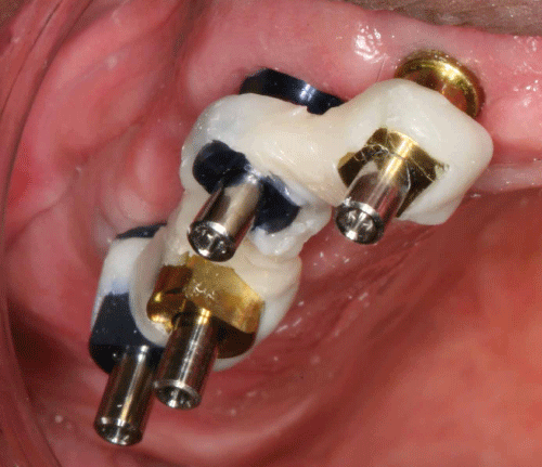
- A heavily nano filled composite resin (Premise; Kerr Dental Products, Orange, CA) is expressed from its injection capsule across the facial surface of one coping and extended to the adjacent coping to form a bar of resin between the two adjacent copings. The capsule expresses a 2 mm thickness of the resin and it is pressed into intimate contact with the copings using a gloved finger. The manufacturer of this resin recommends 40 seconds of light-polymerization for thicknesses up to 2.5 mm and the recommended time is used for each increment of resin. The light-polymerization was accomplished using an L.E. Demetron II unit (Kerr Dental Products, Orange, CA). Another bar of resin is then expressed lingually and pressed into contact with the already polymerized facial bar so as to encircle both impression copings and thicken the interproximal bar of resin. The second bar of resin is polymerized and then the process repeated so as to connect all the copings into one unit (Figure 2).
- A screw rotation test is then used to verify the seating of the impression copings [13]. The one screw test is used by loosening all the impression coping screws and then torque-tightening one screw at either end of the connected copings in the verification jig. Next, the other most posterior screw is tightened using a hand screwdriver until contact is achieved between the metal components. After contact between the impression coping and the implant abutment is obtained, the amount of circumferential rotation of the torque driver required to obtain 10NCm of torque is observed. It will be noted that the handle of the torque driver makes very little circumferential rotation when the metal parts are in intimate contact with each other, indicating good fit of the impression coping on the abutment. The process is repeated between the end coping and other intermediary impression copings. The degree of screwdriver rotation from initial metal contact to a torque-tightened level serves as a good index to the degree of passive fit between the metal parts. With this technique there is very little screwdriver rotation from the point of physical contact between the metal parts to completion of torque tightening, indicating that a low shrinkage composite resin can be effectively used to simultaneously connect multiple impression copings without the need for sectioning the connections and subsequently re-attaching the sections to compensate for polymerization shrinkage as is required when using an autopolymerizing acrylic resin.
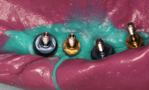
- An impression tray with an occlusal opening that fits over the connected impression copings is then used for the definitive poly (vinyl siloxane) impression (Figure 3).
- Albrektsson T, Brånemark PI, Hansson HA, Lindström J. Osseointegrated titanium implants. Requirements for ensuring a long-lasting, direct bone-to-implant anchorage in man. See comment in PubMed Commons below Acta Orthop Scand. 1981; 52: 155-170.
- Skalak R. Biomechanical considerations in osseointegrated prostheses. See comment in PubMed Commons below J Prosthet Dent. 1983; 49: 843-848.
- Kohavi D. Complications in the tissue integrated prostheses components: clinical and mechanical evaluation. See comment in PubMed Commons below J Oral Rehabil. 1993; 20: 413-422.
- Jemt T, Book K. Prosthesis misfit and marginal bone loss in edentulous implant patients. See comment in PubMed Commons below Int J Oral Maxillofac Implants. 1996; 11: 620-625.
- Lee H, So JS, Hochstedler JL, Ercoli C. The accuracy of implant impressions: a systematic review. See comment in PubMed Commons below J Prosthet Dent. 2008; 100: 285-291.
- Smith DL, Schoonover IC. Direct filling resins: dimensional changes resulting from polymerization shrinkage and water sorption. See comment in PubMed Commons below J Am Dent Assoc. 1953; 46: 540-544.
- Craig RG. Restorative dental materials. 7th ed. St Louis: CV Mosby. 1985; 469.
- Mojon P, Oberholzer JP, Meyer JM, Belser UC. Polymerization shrinkage of index and pattern acrylic resins. See comment in PubMed Commons below J Prosthet Dent. 1990; 64: 684-688.
- Kim S, Nicholls JI, Han CH, Lee KW. Displacement of implant components from impressions to definitive casts. See comment in PubMed Commons below Int J Oral Maxillofac Implants. 2006; 21: 747-755.
- Peutzfeldt A. Resin composites in dentistry: the monomer systems. See comment in PubMed Commons below Eur J Oral Sci. 1997; 105: 97-116.
- Braem M, Lambrechts P, Van Doren V, Vanherle G. The impact of composite structure on its elastic response. See comment in PubMed Commons below J Dent Res. 1986; 65: 648-653.
- kerrdental-composites-premise-techinfo-2.
- Kan JY, Rungcharassaeng K, Bohsali K, Goodacre CJ, Lang BR. Clinical methods for evaluating implant framework fit. See comment in PubMed Commons below J Prosthet Dent. 1999; 81: 7-13.

Figure 1: Impression coping hand-tightened on the implants.
Figure 2: Verification jig fabricated using a heavily nano filled lightpolymerized composite resin.
Figure 3: Final implant level impression with connected impression copings embedded within poly (vinyl siloxane) impression material.
Discussion
The described technique provides an easy and efficient method for fabricating an intraoral verification jig made using a non-flowable heavily nano filled composite resin. Because of the very low polymerization shrinkage of the composite resin and the reduced time required to light-polymerize the resin compared to autopolymerizing acrylic resins, the accuracy with which impression copings have recorded the implant positions can be quickly evaluated before making the final impression.
References

