Abstract
The crush-leach process was investigated as a method to treat GEN IV simulated ceramic-coated reactor fuel. Simulated ceramic-coated fuel was prepared using fine carbon as a coating and surrogate elements for fuel, the method retained the bulk of the carbon components in elemental form, which is favorable for achieving waste reduction goals. Simulated ceramic-coated fuel was crushed and nitric acid was added to the fines as slurry that led to rapid and effective leaching of the heavy metal. The leaching process of simulated crushed ceramic-coated fuel and extraction behavior of the separated leaching solution was tested at the laboratory scale. Results showed that carbon used in the preparation of stimulated fuel was difficult to be separated by filtered, indicating the need to carefully control particle size and/or use alternative solid-liquid separation methods. Foams or emulsions was not observed during the solvent extraction step, which indicated that measurement of the distribution ratios for actinides elements were slightly larger than predicted by previous models. This increase may be due to small concentrations of organics; however the experimental results are not conclusive. Although the results do not strongly indicate effects by a contaminating organic agent, the organic species may exist in small concentrations. Such an organic species could affect the extraction behavior of the solvent if it accumulates over time.
Keywords: GEN IV simulated fuels; Leaching process; Solvent extraction; Nuclear fuels microstructure
Introduction
Currently fuel used in reactor cores is typically enriched cerium dioxide which preceded cerium metal in Magnox reactors due to its ability to achieve higher burn up. The desire to increase this fuel burn up, including higher temperature, intense irradiation and increased heavy metal density in the core, new materials must be found that possess the required Thermo physical properties. Nitride and carbide fuels have received much attention due to their potential application in Generation IV as they combine both the advantages of metallic and oxide fuel [1,2,3]. Cerium carbide
[1] and uranium nitride have high heavy metal density, high thermal conductivity and minimal impact on neutron spectrum [2]. The unloaded fuel from the core of the open fuel cycle disposed directly contains some fissionable isotopes of uranium and plutonium. These isotopes can be recovered using an extraction reprocessing process (PUREX) to be returned back into the fuel cycle. As the majority of the existing spent fuel exist as an oxide fuel, carbothermic reduction of the oxide powders is the most attractive route for large scale production of non-oxide fuels. Methods of carbothermic reduction and nitridation of oxides are based on mixing the oxide powder with a carbon source at(1600-2100°C) under inert atmosphere, followed by further heat treatment under the same temperature range under hydrogen-nitrogen atmosphere (10% H2) to complete the reaction and remove the excess carbon. The basic mechanism of this carbothermic reduction and nitridation method is given by equation (1):
MO2 + 3C →MC + 2CO→MN + CH4 (1)
Thermophysical properties of ZrN and (Pu0.25,Zr0.75) N solid solutions have been reported by Basini et al [4]. They produced samples of ZrN and (Pu,Zr)N by pressing pellets from powders with geometrical densities of (70% and 89%TD) respectively. They report the scarcity of thermal conductivity data with few available not reproducible results and thermal conductivity for zirconium nitride between 15-20 W m-1 K-1 at 427-2027 °C. Conductivity values were then corrected to fully dense materials using a modified Maxwell-Eucken correlation (equation 2) [5].
KTD = K / ((1 – p)/(1+βp)) (2)
where, KTD is the thermal conductivity of fully dense material,
p is the porosity fraction of the material and β is a coefficient (0.5≤ β ≤ 3) .
The calculated thermal conductivities were found to be between (35-40 W m-1 K-1) over the same temperature range. Thermal properties including the specific heat, thermal diffusivity and thermal conductivity of ZrN have also reported by Cirielloet al [5]. The analysis was performed with commercial ZrN powder reduced carbothermic into sintered pellets achieving a density of (82.4% TD) as measured by the immersion method and 80.6% TD as measured by the geometrical method, indicating that the open porosity is (~10.2vol%). The authors noticed that the development of an oxide layer on the surface of the pellets as indicated by XRD was undetectable. After correction of density, the thermal conductivity was found to be (15-30 Wm-1K-1)at (247-1197°C), which is in good agreement with that given by Hedge et al. [6].
The Japanese Atomic Energy Agency has also proposed ZrN and TiN as diluent materials for GFR fuel. Both materials showed higher thermal conductivity and melting temperature values than that given by the actinide mononitrides and are free from phase transformation and offer a stable structure. Arai et al [7] noted that, although both diluent materials have the same crystal structure, ZrN is likely due to formation of solid solution with PuN, while the solubility of PuN in TiN is negligible. Arai and Nakajima [7] and Minato et al [8] prepared plutonium nitride pellets containing ZrN and TiN as inert matrices using PuO2 powder. The carbothermic reduced PuN was prepared by mixing PuO2 and graphite with 2:2 molar ratio. The powders were then compacted into discs at 100MPa and heated in N2 atmosphere at (1550 °C) for (10 h), followed by heating at (1450°C) for (20 h) in hydrogen / nitrogen atmosphere.
Streit et al [9,10] studied the suitability of carbothermic reduction in fabrication of zirconium nitride matrix using the sol-gel method and the dry powder rout. The sol- gel route was used to fabricate microspheres of ZrN, Ce0.2Zr0.8N, Nd0.2Zr0.8N, U0.2Zr0.8N, and Pu0.2Zr0.8N. The dry powder rout is the process of carbothermic reduction and nitridation which was split into two mechanisms. First carbothermic reduction of cerium oxide CeO2 to cerium carbide (CeC2) powder, second nitridation of CeC2 to CeN were performed.
Microstructures of the spheres showed a uniform distribution of pores (~5-10 μm diammeter) due to gas release from the reduction reaction and a second phase which is proposed as unreacted oxide and carbon black. Densities of the spheres were between (91-103 %) and unreacted oxide phases or carbon is stated as possible cause of greater than (100% TD). However, no quantitative analysis of these phases or carbon and oxygen content is noted. Nakagawa et al [11] reported the formation of uranium and cerium nitrides from their respective carbides using NH3 or N2/H2 gas mixtures. They noted that in the first step, the reduction of ceria needs a cerium oxide to carbon ratio of (1:4.8 wt.%) to complete the reaction. However, XRD of cerium carbide reacting with ammonia showed the presence of graphite.
The powders of PuN and ZrN were mixed in ratio of (40Pu:60Zr wt%), and powders of PuN and TiN were mixed in a ratio of (50Pu:50Tiwt%). The mixed powders were compacted into discs and heated in hydrogen/nitrogen atmosphere for 5 h. This step was repeated three times, then the discs were ground and compacted into green pellets at 300 MPa and sintered in argon atmosphere at (1730°C) for (5 h), followed by heating in a hydrogen / nitrogen atmosphere at (1400°C) to control stoichiometry. Nitrogen, carbon and oxygen quantities were determined by combustion gas chromatography, inert gas fusion coulometer and high frequency heating coulometer, respectively.
The aim of this work is to fabricate fuel forms using cerium nitride as an actinide surrogate by the carbothermic reduction of cerium oxide. Microspheres of CeN will also be produced via the Internal Gelation Method (IGM) and carbothermic reduction. Optimisation of sol formulations using cerium ammonium nitrate, HMTA and urea in the fabrication of cerium oxide microsphere have been studied. Cerium oxide microspheres doped with carbon black will be investigated and reactive sintering was studied.
Experimental
Ceramic Fabrication
As studying irradiated nuclear fuel is surrounded by a high radiation field, studying such material is complicated. This is the reason why scientists have been developing simulated nuclear fuel (SIMFuel). SIMFuel is an un-irradiated analogue of irradiated ceramic, produced by doping a cerium oxide (CeO2) matrix with a series of nonradioactive elements in appropriate proportions that can replicate the chemical and microstructural effects of irradiation on UO2 fuel at various degrees of burnup in a reactor. Nonradioactive elements in SIMFuel can represent most fission products (FPs) present in an irradiated including oxides dissolved in a matrix, metallic precipitates and oxide precipitates [10].
FPs in a SNF can be typically classified into four groups [1,10,11].
1. Inert gases and volatile elements: Xe, Kr, He; I, Br, (Rb, Cs, Te)
2. Metallic precipitates: Ru, Pd, Rh (Tc), Mo, Ag, Cd
3. Oxide precipitates: Ba, Zr, Mo, (Rb, Cs, Te, I)
4. Oxides dissolved in the UO2 matrix: Sr, Zr, Y, La, Ce, Sm, Nd, Pu, Np
When fabricating SIMFuel, the oxides of these elements are used and some are later reduced in a reducing atmosphere, typically in Ar-10at% H2 in order to replicate the chemical state and microstructure of the last three FP classes. The elements listed in 3 represent all major FPs, except the volatile elements, and comprise the majority of all expected solid FPs. In some cases elements with similar chemical behaviour are represented by a single elements. [11] These tables are considered further in section
2.3. In the present study FISPIN was used to estimate concentrations of FPs. FISPIN is a fuel depletion code. It calculates the changes in the numbers of atoms of the nuclides of various species – heavy isotopes or actinides, FPs, and structural or activation materials – as a sample of nuclear fuel element is subjected to periods of irradiation and cooling. [12]. For this study the most important detail is the amount of each isotope because it can be used for calculating the composition of simulated fuel. It is also important to understand some of its main radiological features. In this section these are highlighted and described in detail. To produce the tables and figures below 43 GWd/t U burn up dataset is used except as stated otherwise.
In figure1 the number of isotopes can be seen after various times following discharge from the reactor. The number of inactive isotopes is constant but the number of active isotopes is decreasing due to radiation decay. The most radioactive and dangerous short half-life isotopes, such as 90Sr and 137Cs decay within the first 1000 years, but some of the isotopes with longer half-life are present even after geological times.
(Figure 2) shows the weight distribution of the most frequent elements excluding 238U. Only seven isotopes are radioactive and all of them have a long half-life. The weight of the rest of the isotopes present in the spent fuel is less, than 1000 grams, but typically only a few grams in one tonne of fuel. Radioisotopes in the first twenty isotopes have a long half-life which means that their activity is low and they are not harmful to the environment.
In figure 3 the most radioactive isotopes present in fuel can be seen. It is striking that four species (137Cs, 137mBa, 90Y and 90Sr) have much greater activity than the rest of the active isotopes. The level of the activity is similar in the first and second as it is in the third and fourth cases. The connection between these pairs is discussed below.
Table 1indicates the weight of isotopes which have high activity in fuel. One of the members of the highly radioactive pairs has very low weight. It is also revealed that these four isotopes. Investigating the connection between the 90Sr and 90Y and the 137Cs and 137mBa it is now clear that the 90Y is a daughter isotope of the 90Sr and similarly the 137mBa is a daughter isotope of the 137Cs. Referring to Table 1, 90Y and 137mBa has extremely small mass. It is because they are short-lived isotopes and as soon as the mother core decays into these isotopes they immediately decay further into stable isotopes-which are present in the FPs in significant weight.
Isotope
Average
mass (g)CS137
147.15
BA137M
2.25E-05
Y 90
0.0148
SR 90
58.98
AM241
771.79
PU238
78.21
PU241
6.87
PU240
2993.00
PU239
2664.50
U 235M
5.37E-06
Table 1: Weight of the most radioactive isotopes.
Results and Discussion
Ceramic Fabrication
Five Iterations of carbothermic reduction parameters are given in (Table 1). XRD spectra of reactant products (Figure 1 & 2) reveal that all peaks in iterations 4 and 5 correspond to tetragonal CeC2 with no oxide phase. Incomplete reactions in iterations 1 and 2 may be due to the form of the sample. A pellet did not allow complete release of CO compared to a loosely packed powder, which may slow the reaction. EDX analysis (Figure 3) reveals the presence of C, N and O light elements in the sample. Free carbon from unreacted materials is also present in the samples.
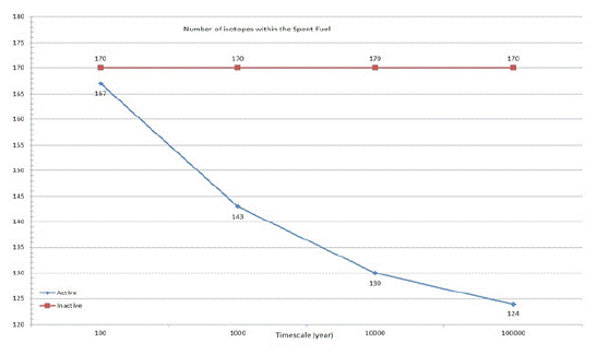
Figure 1: Number of isotopes within the Spent Nuclear Fuel after various times into the future.
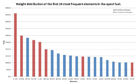
Figure 2: Weight distribution of the first 20 most frequent isotopes.
Figure 3: The most radioactive isotopes in the SNF.
As no oxide phase was detected by XRD, nitridation was attempted. In these experiments the sample were placed in a crucible and heated to in a hydrogen doped nitrogen atmosphere (10% hydrogen, 90% nitrogen). Reaction parameters are given in (Table 2). In the first iteration an alumina crucible was used, but no product was retrieved due to possible reaction between the crucible and sample and so subsequent reactions used zirconia crucibles.
    Iteration

    Form

    Temperature

    Time/h

    Atmosphere

    Phase by XRD


    /oC


    C-1

    Pellet

    1500

    12

    Vacuum

    CeO2,CeC2,C


    C-2

    Pellet

    1800

    5

    Argon (100%)

    CeO2,CeC2,C


    C-3

    Powder

    1800

    5

    Argon (100%)

    CeO2,CeC2,C


    C-4

    Powder

    1800

    12

    Argon (100%)

    CeC2,C


    C-5

    Powder

    1800

    12

    Nitrogen (100%)

    CeC2,C
Table 2: Reaction parameters for carbothermic reduction of CeO2.
Iteration
(N-nitridation)Crucible
Temperature/oC
Dwell time/h
Atmosphere
N-1
Alumina
1800
6
H2(10%)N2(90%)
N-1
Zirconia
1800
6
H2(10%)N2(90%)
N-1
Zirconia
1800
8
H2(10%)N2(90%)
Table 3: Reaction parameter for nitridation experiments of CeC.
    Layer

    Material

    Dimension

    Density (g/cm3)

    Volume (cm3)

    Mass (g)

    wt %


    Kernel

    Zirconia

    500 μm (diam)

    5.6

    6.54E-05

    3.67E-04

    43.6


    Buffer layer

    Porous carbon

    100 μm (thickness)

    0.95

    1.14E-04

    1.08E-04

    12.9


    I-PyC

    Pyrolitic carbon

    40 μm (thickness)

    1.9

    6.89E-05

    1.31E-04

    15.6


    SiC

    Silicon carbide

    35 μm (thickness

    3.2

    7.31E-05

    2.34E-04

    27.9


    Coated Particleas a whole


    850 μm (total diam)

    2.61

    3.22E-04

    8.40E-04

    100.0


    Zirconia


    3.67E-04

    43.6


    Carbon


    2.39E-04

    28.5


    SiC


    2.34E-04

    27.9


    TOTAL


    8.40E-04

    100.0


    aDensity of each layer is from various references and is    used together with the dimensions to calculate the volume, mass, and weight    fractions of each constituent.
Table 3-1: The constituents of the coated zirconia fuel surrogate based on particle characteristicsa.
The reacted powder from itration 2 yielded an orange powder, XRD of the reacted powders, shown in (Figure 4), matched a phase patterns for a Ce2ON2 and Ce2O3 phase. However, EDX analysis no nitrogen was detected as shown in (Figure 5), indicating the presence of Ce2O3 phase. Carbon peaks in iteration 3 may be present due to unreacted carbon powder from the carbothermic reduction, which was not the case in iteration 2 due to the higher sintering temperature.
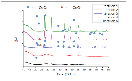
Figure 4: Comparison between experimental XRD of reacted powder.
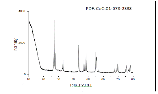
Figure 5: XRD of powder obtained from iteration C-4, all peaks correspond to tetragonal CeC2.
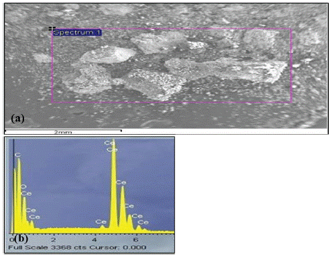
Figure 6: (a) SEM of experimental powder iteration C-4. (b) EDX spectrum from square area.
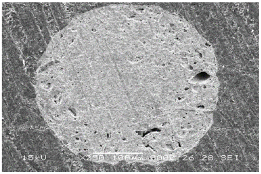
Figure 7: SEM image of CeO2 microsphere produced by IGM, sintered at 1400 OC.
Solvent Extraction
Equilibration of fresh UREX solvent with aqueous solutions having the measured cerium and nitric acid concentrations was modeled with both the AMUSE (ver. 3.02e) and SEPHIS (Mod 4) codes. The calculated distribution ratios are listed in (Table 2) with the experimental values. As shown in the table, the nominal measured distribution ratios are similar to, but larger than, those predicted by either model. The lower experimental values are very close to the model predictions but are generally slightly higher. These data indicate that the aqueous phase is not contaminated with organic phase, due to the action of soluble organic species arising from the carbon constituents. Otherwise, the measured distribution coefficients would be lower than those predicted by the models.
Equilibration of fresh UREX solvent with aqueous solutions having the measured cerium and nitric acid concentrations was modeled with both the AMUSE (ver. 3.02e) and SEPHIS (Mod 4) codes. The calculated distribution ratios are listed in (Table 2) with the experimental values. As shown in the table, the nominal measured distribution ratios are similar to, but larger than, those predicted by either model. The lower experimental values are very close to the model predictions but are generally slightly higher. These data indicate that the aqueous phase is not contaminated with organic phase, due to the action of soluble organic species arising from the carbon constituents. Otherwise, the measured distribution coefficients would be lower than those predicted by the models.
A homogenous sol mixture is essential for gelation to produce complete uniform spheres, which may overcome the cracking problem seen in the pyrolysis step. An even distribution of carbon and CeO2 particles is also required for the sintering stage to achieve complete carbothermic reduction and to ensure the linear shrinkage of the sphere at the volume changes during the reaction.
Conclusion
Cerium carbide could be produced via carbothermic reduction of ceria with no ceria phases as identified using XRD by increasing temperature and time. However, nitridation has not been achieved with reactions giving Ce2O3, using oxygen of (<0.0001 ppb). The product was analysed immediately by XRD to avoid any room temperature oxidation. Nitridation experiments was performed in ammonia atmosphere which has greater activity of nitridation process. The reason for the systematically higher measured distribution ratios needs to be understood. It could be due to one or more of the following: (1) the phases change volume appreciably upon equilibration, violating the assumptions built into Eq. 1; (2) there are systematic errors in the experimental methodology; (3) the computer models deviate from reality at the high nitric acid concentrations around 7 M, as in these leachate solutions; or (4) an organic compound is formed that alters the extraction behavior. The latter could be caused by an organic compound that distributes to the organic phase and enhances the extraction of actinides elements by tri-n-butyl phosphate (TBP). However, the control sample prepared also exhibited a high distribution ratio. It is likely that either postulate 2 or 3 is the cause of the deviations from the models. Production of surrogate fuel pellets using CeN as an actinide surrogate can be fabricated. Group IV nitride materials also exhibit a broad range of non-stoichiometry.
References
- PA Demkowicz, B Liu, JD Hunn, Coated particle fuel: Historical perspectives and current progress. Journal of Nuclear Materials. 2018, in press.
- S Starikov, M Korneva. Description of phase transitions through accumulation of point defects: UN, UO2 and UC. Journal of Nuclear Materials. 2018; 510: 373-381.
- Y Arai, K Minato. Fabrication and Electrochemical Behaviour of Nitride Fuel for Future Applications. Journal of Nuclear Materials. 2005; 344: 180-185.
- V Basini, JP Ottaviani, JC Richaud, M Streit, F Ingold. Experimental Assessment of Thermophysical Properties of (Pu,Zr)N. Journal of Nuclear Materials. 2005; 344: 186-190.
- A Ciriello, VV Rondinella, D Staicu, J Somers. Thermophysical Characterization of Nitrides Inert Matrices: Preliminary Results on Zirconium Nitride. Journal of Nuclear Materials. 2007; 371: 129-133.
- JC Hedge, JW Kopec, C Kostenko, JL Lang. Thermal Properties of Refractory Alloys, US Air Force Report, ASD-TDR 63-597. 1963.
- Y Arai, K Nakajima. Preparation and Characterization of PuN pellets containingZrN and TiN . Journal of Nuclear Materials. 2000; 281: 244-247.
- K Minato, M Akabori, M Takano, Y Arai, K Nakajima, et al. Fabrication of nitride fuels for transmutation of minor actinides , Journal of Nuclear Materials. 2003; 320: 18-24.
- M Streit, F Ingold, M Pouchon, LJ Gauchler, J-P Ottaviani. ZrN as Inert Matrix for fast systems, Journal of Nuclear Materials. 2003; 319: 51-58.
- M Streit. Fabrication and characterization of (Pu,Zr)N Fuels, University of Basel, Swizerland, Ph.D. Thesis. 2004.
- T Nakagawa, H Matsuoka, M Sawa Hirots, M Miyake, M Katsura. Formation of Uranium and cerium nitrides by reaction of carbides with NH3 and N2/H2 Stream, Journal of Nuclear Materials. 1997; 247: 127-130.
- PC Stevenson, WE Nervik. Radiochemistry of rare earths, Sc, Yi &Ac, National Academy of Sciences, National Research Council Nuclear Series, NAS-NS 3020, Feb. 1961.
- JL Collins, MF Lioyd, RL Fellows. The Basic Chemistry Involved in the Internal-Gelation Method by pH measurements. Radiochimca Acta. 1987; 42: 121-134.
- NJ Ashley, RW Grimes, KJ McClellan. Accommodation of Non- stoichiometry In TiN and ZrN, Journal of Material Science. 2007; 42.
