Special Issue – Clinical Neurophysiology
Austin Neurol & Neurosci. 2017; 2(1): 1018.
Segmented Leads for Deep Brain Stimulation in Patients with Parkinson’s Disease
Bour LJ*
Department of Neurology/Clinical Neurophysiology, Academic Medical Center, University of Amsterdam, Netherlands
*Corresponding author: Lo J. Bour, Department of Neurology/Clinical Neurophysiology, Academic Medical Center, University of Amsterdam, Netherlands
Received: April 04, 2017; Accepted: May 15, 2017; Published: May 22, 2017
Limitations of Conventional DBS Leads
Deep Brain Stimulation (DBS) of the Sub-Thalamic Nucleus (STN) is an effective treatment for Parkinson Disease (PD) [1]. The efficacy of DBS may be limited by current spread into adjacent structures, inducing side effects such as muscle contractions, dysarthria, and cognitive or behavioral disturbances [2]. The goal is to have the largest Therapeutic Window (TW) as possible, i.e. the largest difference between the lowest threshold for therapeutic effect and the highest threshold for adverse effects. The most effective position for obtaining the best therapeutic effect in PD has been demonstrated to be the dorsolateral area of the STN. This means that this area in fact is considerably smaller than the size of the STN itself (about 40%) and, therefore, for STN-DBS precise targeting within an accuracy of 1-2 mm is required. Conventional DBS leads (CC) have not been changed in the past decennia and harbor 4 ring-shaped contacts. Adjacent contacts from center to center are separated by 2 mm. In total the distance from the center of the most dorsal contact point #3 to the center of the most ventral contact point #0 subtends six millimeter in depth (Figure 1).
Imaging in the past decennia has improved considerably by high precision 3D MRI and its ultimate accuracy is about 1-2 mm [3]. Other inaccuracies in the surgical procedure including the final placement of the lead may add up to the total inaccuracy of the procedure [4]. This means statistically that in some of the patients the deviation of the optimum target position will be larger than 1-2 mm. CC leads do not have sufficient degrees of freedom to correct sufficiently for too large positional error. Particularly when the target is located 2-3 mm too lateral or too medial the current has to be increased considerably such that adjacent structures are stimulated, leading to unwanted adverse effects (Figure 2) and a decrease of the TW.

    Figure 2:  Schematic presentation of a coronal plane of the brain at the level of the STN is shown. Cpi.p indicates internal capsule, Stn indicates the subthalamic
nucleus, Ru indicates the red nucleus. A) At the left side of Figure 2A the blue circular volume defines the area of activation at a current of 3 mA around the activated
contact point #1 of a conventional electrode with four ring-shaped contact points. At the right side of Figure 2A the transection in the coronal plane of the lead
(grey dot) and the activation area (blue circle) is shown. Too lateral placement of the lead with this current leads to suboptimal activation of the STN and unwanted
activation of the internal capsule. B) Figure 2B shows exactly the same arrangement as in Figure 2A except that the conventional lead is replaced by a segmented
lead with 32 contact points of which each has his specific orientation and depth. In this case the green activation area is related to ring-mode stimulation of the
segmental lead. C) Figure 2C shows an activation pattern of the segmental lead in steering-mode. Too dorsolateral placement of the lead can be compensated for
by steering the current into the ventromedial direction resulting in an optimal stimulation of the STN, whereas avoiding unwanted stimulation of the internal capsule.
Improvements with Segmented Leads
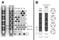
To overcome this problem recently two segmented electrodes have been used in Parkinson patients, namely a 32-contact HD lead (Figure 1A) and an eight-contact Vercise lead (Figure 1B), which have a larger amount of, smaller and more closely located contacts. The 32-contact HD lead (Medtronic Eindhoven Design Center) enables a higher precision in depth but it also can steer current selectively into different directions such that the TW can be increased compared to conventional ring stimulation [5-9]. It has been shown per-operatively in PD patients that with steering the TW can be increased. The Vercise lead (Vercise PC, Boston Scientific, Valencia, CA) can steer current selectively into different directions but has no higher precision in depth compared to the CC lead (Figure 1B). Also with this lead in an early postoperative time period an increased TW was observed [10]. However, the orientation of the segmented lead with respect to the structures that have to be activated is essential. Furthermore, the Vercise lead compared to the HD lead has only steering possibilities at the two middle levels, which are split into three segments (Figure 1B). With the HD lead each level is split up into four segments where each consecutive level is shifted 45 degrees (Figure 1A).

    Figure 1:  A) A comparison of the conventional CC lead and a 32-contact HD
lead with its dimensions is shown at the left. The array of contacts at the right
shows the arrangement of the 40 contacts in a flat plane. The twelve contacts
shown in medium grey (R0,R1,R2) show the activation pattern in ring-mode,
the four dark grey contacts (R4,R5,R6) show the steering mode with a starshaped
pattern, the four black contacts (R7,R8,R9) show the steering mode
with a diamond-shaped pattern. B) Comparison of the conventional CC
lead with the Vercise lead with its dimensions is shown at the left side. Only
the two middle ring shaped contacts are split into three segments as more
clearly is shown at the right side of 1B. The four transections demonstrate the
importance of the orientation of this lead.
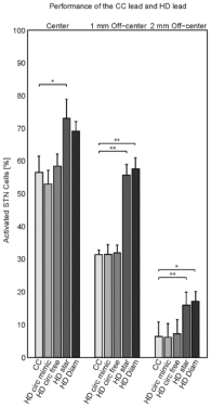
Although the results with the new directional leads are promising the main problem is that it is difficult to determine the position of the lead with respect to the structures that have to be stimulated and which structures have not to be stimulated. The Vercise lead comes with a pulse generator that is capable of Multiple Independent Current Control (MICC) and modeling studies suggest additional clinical benefit may be achieved when coupling this directional lead with MICC designs [11]. Another modeling study [12] has demonstrated that an off-center displacement of the HD-lead inside the STN could be compensated for by a steering-mode: the amount of activated neuron cells could be increased compared to a ring-mode stimulation (Figure 3). However, at the moment current steering requires increased programming burden with trial and error. A longer period of clinical rating of rigidity and adverse affects is required which may become exhausting for the patient and less objective for the clinician [10].

    Figure 3:  The performance of the five stimulation modes, i.e., the conventional
CC, the ring-modes HD circ(ular) mimic and HD circ(ular) free, and the
steering modes HD star and HD diam(ond). Bars denote mean values with
standard deviations of the percentage of activated STN cells after stimulation
for the five datasets per lead location each with random distributions of the
cells/fibers in the neural populations. Significant differences after Bonferroni
correction for multiple comparisons (n=6) are indicated with one asterisk
(p<0.05) or two asterisks (p<0.01).
Local Field Potential (LFP) Recording Used for Positional and Directional Feedback
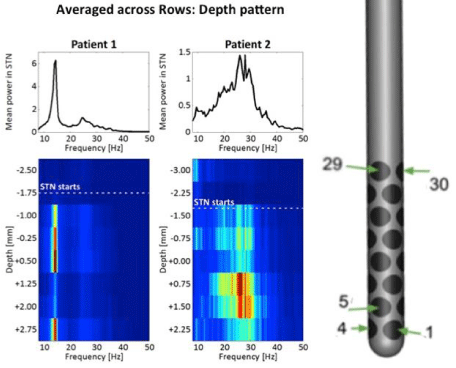
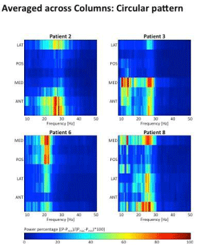
A way to overcome the burden of programming a segmented lead and to avoid tests with virtually endless combinations, recording of Local Field Potentials (LFPs) previous to stimulation should guide the direction and height of current steering. A recent study [8] has demonstrated that with a high-density lead of 32 or even 40 contacts the resolution is sufficient to locate the beginning and end of the STN as well as the direction of the highest beta power inside the STN with respect to the high-density lead position. Here the beta power (LFP frequency content between 12-35 Hz) is the most important part of the recorded signal, since it is particularly limited to the STN including the sensomotoric part. Figure 4 demonstrates clearly how the beginning of the STN is found by a sudden increase in beta power across the array of 32 contacts. Figure 5 shows that the distribution of power around the segmented lead in anterior, medial, posterior and lateral direction varies in four different patients. In each patient beta power is largest into a certain direction.

    Figure 4:  Two columns on the left show in two patients on top the spectral
distribution of the LFP averaged across all contacts and on the bottom the
colour coded (for scaling of colour code see Figure 5) spectral distribution
as a function of depth. LFPs are averaged across each row (four contacts/
row). The dotted white line indicates the beginning of the STN. For patient 1
maximum beta activity is at a depth of +0.5 mm, for patient 2 the maximum
beta activity is at +0.75 mm. Note the difference in spectral distribution
between the two patients. In patient 1 and 2 a beta peak is found at about 14
Hz and 26 Hz, respectively. At the right the high density lead with 32 contacts
is shown.

    Figure 5:  The four boxes show in four patients the spectral distribution of
the LFP averaged as a function of direction (eight contacts/column). The
colour coding is indicated at the bar below.MED, POS, LAT, ANT means
into medial, posterior, lateral and anterior direction, respectively. In patients
2,3,6,8 maximum activity is found in the anterio-lateral, medio-anterior,
medio-posterior and anterio-medial direction, respectively.
Thus, provided a high-density lead is being used, LFPs can be used per-operatively to locate the beginning and end of the STN as a positional feedback, without using Micro Electrode Recording (MER). This can be achieved much quicker than with MER, since only a single insertion of the high-density lead with simultaneous recordings of all the contact points is required. Secondly, if a high-density lead is being used for stimulation post-operatively, sensing possibility of the contact points may reveal the position of the lead with respect to the highest beta power inside the STN. This chronically obtained information can be used for directional feedback to steer the current into the desired direction. It must be noted that the Vercise lead appears to be not very well designed for positional and directional feedback. Sensing from the contacts of this lead is of much lower resolution than of a high-density lead.
Conclusion
To have guidelines for the position of a DBS lead and the direction of current steering with a segmental lead, high resolution LFP recording is desirable. Although the Vercise lead gives the opportunity of steering DBS it does not have the resolution to perform accurate LFP recordings and, therefore, a high-density segmented lead is needed. The introduction of a high-density lead for steering together with accurate and high-density recording of LFP beta power in the future will help the clinician both to correct for slight displacements of the DBS lead with respect to the optimal DBS target as well as to speed up the programming of these newly developed segmental leads.
References
- Krack P, Hariz MI, Baunez C, Guridi J, Obeso JA. Deep brain stimulation: from neurology to psychiatry? Trends Neurosci. 2010; 33: 474-484.
- Tommasi G, Krack P, Fraix V, Le Bas JF, Chabardes S, Benabid AL, et al. Pyramidal tract side effects induced by deep brain stimulation of the subthalamic nucleus. J Neurol Neurosurg Psychiatry. 2008; 79: 813-819.
- Schuurman PR, de Bie RM, Majoie CB, Speelman JD, Bosch DA. A prospective comparison between three-dimensional magnetic resonance imaging and ventriculography for target-coordinate determination in framebased functional stereotactic neurosurgery. J Neurosurg. 1999; 91: 911-914.
- Verhagen R, Schuurman PR, van den Munckhof P, Contarino MF, de Bie RM, Bour LJ. Comparative study of microelectrode recording-based STN location and MRI-based STN location in low to ultra-high field (7.0 T) T2-weighted MRI images. J Neural Eng. 2016; 13: 066009.
- Martens HC, Toader E, Decre MM, Anderson DJ, Vetter R, Kipke DR, et al. Spatial steering of deep brain stimulation volumes using a novel lead design. Clin Neurophysiol. 2011; 122: 558-566.
- Contarino MF, Bour LJ, Verhagen R, Lourens MA, de Bie RM, van den Munckhof P, et al. Directional steering: A novel approach to deep brain stimulation. Neurology. 2014; 83: 1163-1169.
- Pollo C, Kaelin-Lang A, Oertel MF, Stieglitz L, Taub E, Fuhr P, et al. Directional deep brain stimulation: an intraoperative double-blind pilot study. Brain. 2014; 137: 2015-2026.
- Bour LJ, Lourens MA, Verhagen R, de Bie RM, van den Munckhof P, Schuurman PR, et al. Directional Recording of Subthalamic Spectral Power Densities in Parkinson’s Disease and the Effect of Steering Deep Brain Stimulation. Brain Stimul. 2015; 8: 730-741.
- Connolly AT, Vetter RJ, Hetke JF, Teplitzky BA, Kipke DR, Pellinen DS, et al. A Novel Lead Design for Modulation and Sensing of Deep Brain Structures. IEEE Trans Biomed Eng. 2016; 63: 148-157.
- Steigerwald F, Muller L, Johannes S, Matthies C, Volkmann J. Directional deep brain stimulation of the subthalamic nucleus: A pilot study using a novel neurostimulation device. Mov Disord. 2016; 31: 1240-1243.
- Krishnan T, Mustakos R, Steinke GK. 374 Modeling the Effects of Current Steering With Directional Leads. Neurosurgery. 2016.
- van Dijk KJ, Verhagen R, Chaturvedi A, McIntyre CC, Bour LJ, Heida C, et al. A novel lead design enables selective deep brain stimulation of neural populations in the subthalamic region. J Neural Eng. 2015; 12: 046003.