
Clinical Image
Austin J Radiol. 2022; 9(1): 1187.
The Cleanable VP Shunt Illustrations: Clinical Images
Alahmari A*
Radiology Specialist, Department of Radiology, Al-Namas General Hospital, Ministry of Health, Al-Namas City, Saudi Arabia
*Corresponding author: Abdulwahab Alahmari, Radiology Specialist, Department of Radiology, Al-Namas General Hospital, Ministry of Health, Al-Namas City, Saudi Arabia
Received: February 08, 2022; Accepted: February 25, 2022; Published: March 05, 2022
Keywords
VP shunt; Cleanable; Hydrocephalus; New Design
Clinical Image
The aim of this paper is to illustrate the proposed idea by Mr. Abdulwhab Alahmari in the paper entitled “Proposal of a Cleanable VP Shunt for Hydrocephalus” [1]. This illustration will highlight the invention’s important details and illustrate the fundamental parts of the proposed VP shunt (Figure 1-8).
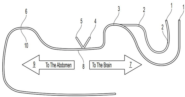
    Figure 1: Illustration of the cleanable VP shunt. 1) Entering points; 2) Siphon shaped catheter; 3) Stainless steel catheter; 4) Cleaning access to the abdomen;
5) Cleaning access to the head; 6) PMMA covers the catheter from outside; 7) To the brain catheter; 8) One direction valve; 9) To the abdomen catheter; and 10)
PMMA covers the catheter from inside.
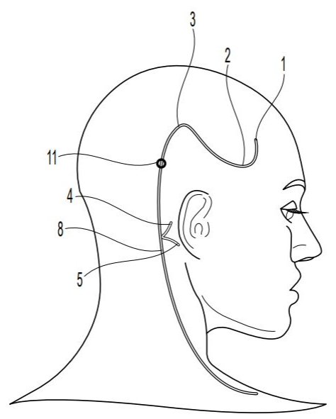
    Figure 2: The cleanable VP shunt in situ. 1) Entering points; 2) Siphon shaped catheter; 3) Stainless steel catheter; 4) Cleaning access to the abdomen; 5)
Cleaning access to the head; 8) One direction valve; and 11) Fixation to the patient’s skull to prevent malposition.

    Figure 3: The distal part of the abdominal part of the shunt. 12) Secondary openings to allow the flow from inside to outside; 13) The distal end; 14) The primary
opening at the end of the catheter, and 15) The secondary openings are designed (convergence) to allow the flow from inside the shunt to outside the shunt and
it prevent the flow back.
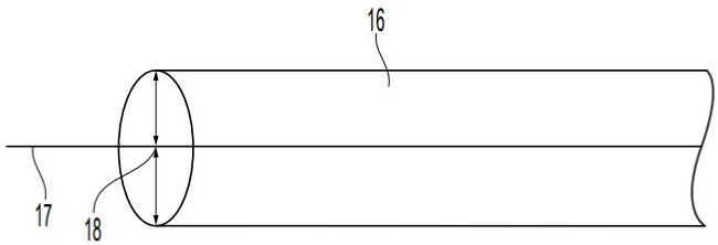
    Figure 4: The cleaning wire thru cleaning access. The cleaning wire must have a mark that the neurosurgeon should not pass this mark. 16) Cleaning access; 17)
Cleaning wire, and 18) The red mark on the wire where the neurosurgeon should not pass it.
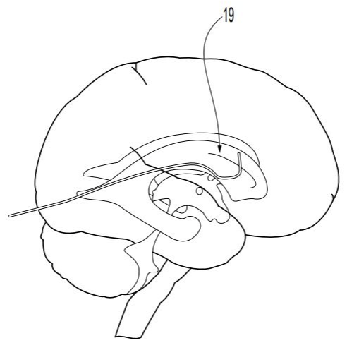
    Figure 5: The required position from the neurosurgeon to place the shunt in a superior position as seen in this illustration. 19) The shunt position allows the entrance
point to be in a superior position.
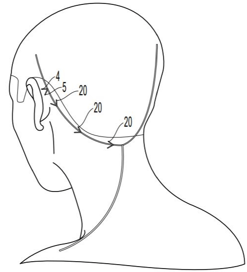
    Figure 6: Fixation of the shunt to the skull to prevent any malposition. 4) Cleaning access to the abdomen; 5) Cleaning access to the head, and 20) Fixation of the
VP shunt to the patient’s skull.
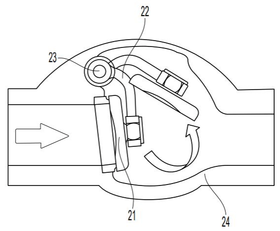
    Figure 7: One way valve located in the abdominal part of the VP shunt. 21) Gatekeeper pushed by pressure and it prevents any flow back from the abdomen, 22)
Arm, 23) Joint to keep the valve closed with low pressure, and 25) valve wall.
