Review Article
Austin J Robot & Autom. 2014;1(1): 6.
Traffic Flow Modeling and Simulation using Micro Intelligent Vehicles
Lindong G1, Zhengchen L1, Ming Y1* and Chunxiang W2
1Department of Automation, Shanghai Jiao Tong University, China
2Research Institute of Robotics, Shanghai Jiao Tong University, China
*Corresponding author: Ming Y, Department of Automation, Shanghai Jiao Tong University, and Key Laboratory of System Control and Information Processing, Ministry of Education of China, Shanghai, 200240, China
Received: October 29, 2014; Accepted: November 28, 2014; Published: December 02, 2014
Abstract
Traffic flow experiments using Micro Intelligent Vehicle (MicroIV) are more efficient and easier to achieve than experiments in actual traffic environment. In this paper, a MicroIV based traffic flow modeling and simulation method is proposed. Firstly, the framework of MicroIV is presented aiming at satisfying the requirements of multi-task and potential extended functions in traffic flow simulation. Secondly, a global path planning approach using time division based hierarchical topology maps, which takes specific traffic rules into consideration, is developed to overcome the difficulties of navigation in micro scale and using hierarchical topology maps for global path planning. Thirdly, in the part of environmental perception, an active vision approach based on improved visual selection attention is proposed to realize more efficient and robust detection of traffic light, and an improved spatial-bag-of-features method is used to make traffic sign recognition more adaptable. Experimental results show that the MicroIV is proved to be suitable for traffic flow simulation.
Keywords: Micro Intelligent Vehicle; Traffic flow simulation; Environmental perception
Introduction
The significance of autonomous driving experiments as well as traffic flow experiments in actual traffic environment have caused widespread concern in recent years [1-3]. With the consideration of many other factors like weather, local laws and safety, however, the implementation of such experiments would lead to a long development period and high research cost. Furthermore, it is unrealistic for multi-vehicle collaboration researches which need multiple intelligent vehicles to participate in. If the experiment could be implemented in a micro scale as those researches which use micro scale models instead of actual objects, these difficulties would be overcame. Thus, a Micro Intelligent Vehicle (MicroIV) used for traffic flow simulation and intelligent vehicle system development is proposed based on this idea. Meanwhile, the experimental platform of micro traffic environment would be carried out indoor. With analysis of urban traffic in detail, micro urban traffic environments is established including different kinds of complex traffic scenes, in which various styles of lanes and intersections are involved. It is more convenient for intelligent traffic system and cooperative vehicle infrastructure system to be tested in such platform where wireless network communications and other measurement techniques are more easily to be installed.
Firstly, as a primary cause of using MicroIV for traffic flow simulation, the hardware configuration must be restricted to limit the cost. As a result of that, advanced sensors like laser scanners, which are standard configuration on a real intelligent vehicle, are not suitable to be deployed on the MicroIV. And in consideration of the size of MicroIV, there is no enough space for a high performance computing platform. But the expected functions of MicroIV must be integrated enough to accomplish the tasks of intelligent vehicles in real traffic situation such as autonomous driving, collision avoidance and traffic light recognition. So a reasonable and reliable hardware configuration is needed. Also the software architecture should be designed as efficiently as possible to optimize computing resources and take the full advantages of the visual sensors.
Secondly, there are still quite a number of difficulties in the navigation and global path planning in traffic flow simulation using Micro Intelligent Vehicles when taken traffic rules into consideration. On one hand, MicroIV could not get a global position through GPS devices because of the application scenario as well as the problem of accuracy. On the other hand, with the complex traffic rules of local intersections and lanes taken into consideration to evaluate the different traffic resource configuration, the micro traffic environment will result in a complex dynamic topology structure which will be quite difficult for global path planning. In order to overcome these problems, Time Division Based Hierarchical Topology Maps are defined in this paper to help locate the position without global position information. Furthermore, a global path planning method is developed on the basis of these maps to acquire a permitted optimal global path for traffic flow simulation that contains time-dependent traffic rules.
Thirdly, traffic light and traffic sign recognition is also one of the key issues among intelligent vehicle researches. Numbers of approaches proposed on traffic sign recognition focused on passive vision model [4-7], which could achieve a good result in local region of image, but difficult to search the relevant ROI rapidly because of lacking an analysis of global statistics of image. But it is obviously that human visual perception can locate ROI rapidly through active vision, and a series of the approximate computation models of active vision have been presented in [8-12]. Among these approaches, an active vision approach called VSA (visual selective attention) proposed in [8-10] could satisfy the real-time and robust requirements of MicroIV. In this paper, a method based on improved selective visual attention approach is employed to optimize the location of ROI which can reduce the computation cost of the detection of traffic sign and traffic light greatly. Then the recognition methods only need to be applied on certain ROI. An improved spatial-bag-of-feature is also proposed to make traffic sign recognition more efficient and adaptable. So traffic sign recognition method employed on MicroIV will be introduced as a whole.
The following paper is organized as followed. The system framework with both hardware and software will be proposed in section II. The time division based hierarchical topology maps for global path planning will be discussed in section III. And the environmental perception approach will be introduced in section IV. Experimental results and conclusions are given in section V and section VI.
Framework
The implementation of MicroIV is still complicated because of the following reasons. MicroIV should be competent for enough functions as same as real vehicles have, and traffic flow simulation needs such a number of vehicles driving in the micro traffic environment that the stability and cost-effective should be ensured. As a consequence of these facts, a robust and strong framework is necessary for both hardware and software.
Hardware framework
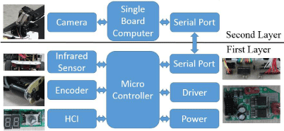
The hardware configuration of MicroIV includes two layers of architecture. The first layer plays a role as a vehicle which is able to realize the steering and speed control according to the instructions it has received. Modules of the first layer includes: engine and steering driver module, speed feedback module, communication module, infrared sensors module, human machine interaction module and power supply module. All these modules are connected and controlled by a micro controller. Relatively, the second layer plays a role as a driver that can give steering and speed instruction based on the vision sensors. The hardware of the second layer is mainly a single-board computer connected with web cameras. The communication between the first layer and the second layer is realized through serial port (Figure 1).
Figure 1: Hardware framework of MicroIV.
Software framework
The software framework is designed for multi-tasks including autonomous driving, collision avoidance, intersection driving, autonomous parking and navigation. The potential extended functions are also considered in this framework. These functions mentioned above are separated into different branches. Basic driving modules contains lane keep module, intersection driving module, lane change module and parking module. Detection and recognition modules contains traffic sign recognition module, traffic light recognition module, intersection check module, obstacle check module, lane change property recognition module and parking area detection module. System managers contains schedule manager, navigation manager, safe manager and communication manager, each of them is respectively responsible for task scheduling, autonomous navigation and path planning, offering safe strategies in different tasks, sending instructions and receiving feedbacks from the first layer (Figure 2).
Figure 2: Software framework of MicroIV.
Global Path Planning with Time Division Based Hierarchical Topology Maps
The issue of global path planning for MicroIV will be more challenging if the detail elements of micro traffic environment are designed more similar to the actual traffic scenes, where a lot of local traffic rules and dynamic lane resources configuration are taken into consideration. For instance, some static traffic rules may be defined in certain intersections that makes the corresponding driving routes (e.g. Turn-Left, Turn-Right and U-Turn) are forbidden which causes the previous global path planning approaches [13,14] hard to achieve a faultless result adaptive to different traffic rules in local intersections. Moreover, these kinds of local specific traffic rules in some intersections and lanes may changing with time interval (e.g. Vehicles-Limit in rush-hours), which leads to the dynamic intersection and lane topology structures in different time periods. In this section, a global path planning approach is developed with the help of time division based hierarchical topology maps to give an effective and reasonable solution to these kinds of problems which means the faultless optimal path can be generated from the dynamic topology structures formed by the complex traffic rules in certain intersections and lanes. The implement of global path planning approach is applied with two steps. In the first step, time division based hierarchical topology maps are designed to simplify the detail description problem of the complex dynamic topology structures modeling. In the second step, a global path planning method will be carried out to obtain the legal optimal path with the overall traffic rules taking into consideration based on related topology maps.
Structure of time division based hierarchical topology maps
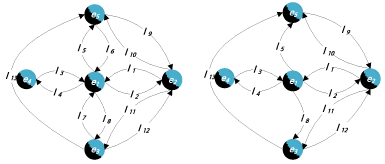
Two layers are established in the structure of time division based hierarchical topology maps. The first layer M1 is composed of a series of global topology maps m1a for the description of dynamic topology relationships between lanes and intersections in the overall micro traffic environment, which are divided into u time intervals. In each time interval a, the topology map m1a is a two-tuple, where E is the set of intersection nodes and L is the set of lane edges (Figure 3).
Figure 3: Example of time division based hierarchical topology maps first layer. (a) m11 0:00~12:00, (b) m12 12:00~24:00.
M1 = [m11, m12,…, m1u] (1)
m1a = (E,L),a∈{1,2,…,u} (2)
E = {e1,e2,…,en},L={l1,l2,…lr} (3)
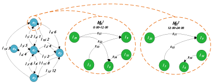
The second layer M2 is made up of the topology-map-bags M2i of every intersection ei. Each M2i includes a series of local topology maps m2ib for the description of the local dynamic topology relationships between lanes lj connected to the intersection ei and permitted driving routes Sik in intersection ei. In each time interval b, the topology map m2ib is a two-tuple, where L is the set of lane nodes and Sib denotes the set of permitted driving, edges (Figure 4).
Figure 4: Example of time division based hierarchical topology maps second layer.
M2 = [M21, M22,…, M2n] (4)
M2i = [M12i, M22i,…, Mvi2i],i∈{1,2…,n} (5)
m2ib = (L,Sib),b∈{1,2…,vi} (6)
Sib = {si1,si2,…,siq} (7)
Global path planning with time division based hierarchical topology maps
There’s no doubt that the conventional global path planning method, for instance the Dijkstra algorithm, can solve the shortest path problem with the monolayer topology map. But this kind of approaches may result in an illegal path due to the local dynamic traffic rules in certain intersections and roads. The global path planning approach proposed here is improved from the classical Dijkstra algorithm to enable the algorithm suitable for the time division based hierarchical topology maps, from which the algorithm could reach a legal global optimal path. The proposed global path planning approach is carried out with several steps. Firstly, the first topology map m1a and the second topology map m2ib in the suitable time interval will be selected according to current time. Secondly, a path generation procedure will be carried out, during the determination whether a lane is belong to the optimal path set, a traffic rules check for local intersection will be applied in the second layer to ensure the reach ability of the chosen lane. If the current lane is reachable, it will be judged further for whether its weight enables itself to be a lane in the optimal path.
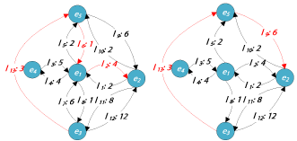
The detail description of the global path planning approach is given as followed, where U is the set of optimal path intersection nodes, W is the candidate set of the other intersection nodes, F is an intersection nodes vector for the record of previous intersection node for each intersection node in the optimal path, P(ei) represents the length from the start intersection node es to current intersection node ei. wji denotes the weight of every lane edge in m1a. The global path planning results of figure 4 is shown in figure 5 where the start node is e3 and the final node is e2 (Figure 5).
Figure 5: Global path planning result. (a) 00:00~12:00, (b) 12:00~24:00.
- Select m1a from M1 according to current time. Turn to 2).
- Initialize U={es}, W=E-{es}, F=(es,es,…,es)n*1, P(es)=0, . Turn to 3).
- . If W=Φ end. Else set Wtemp=W and turn to 4).
- If Wtemp=Φ return to 3). Else set next element of Wtemp to be ei, Wtemp=Wtemp-{ei}. Turn to 5).
- If (ej,ei)∈ m1a, turn to 6). Else turn to 4).
- Select m2ib from M2i according to current time. Turn to 7).
- Set etemp=F(j), lfirst=(etemp,ej), lsecond=(ej,ei). If (lfirst, lsecond)∈ m2ib turn to 8). Else turn to 4).
- If P(ei)>P(ej)+wji, P(ei)=P(ej)+wji, F(i)=ej. Else return to 4).
Environmental perception
The environmental perception methods of MicroIV are restricted because there is neither high performance processer to afford complicated algorithms nor large platform to carry numbers of sensors. So the environmental perception is mostly based on vision information gained from camera, and the algorithms applied in this situation should be very efficient. A suitable approach called visual selection attention (VSA) is introduced here to locate the ROI according to the selected features which is used in detection. The detection of traffic sign is realized in a similar way, and coming up with a method of improved Spatial-bag-of-features to finish the recognition.
Visual selection attention based detection
The traffic light detection approach employed here consists of several steps. First step is preprocessing including image resize and color space transform from RGB to HSI to make the image suitable for VSA. Secondly, a VSA method based on HSI features is used to get the ROI. Then the position of ROI in the origin image is calculated to reach a high resolution of ROI. In the end, a bottom-up detection method is carried out to achieve the final recognition results.
Because the RGB color space is not suitable for the description of a certain color, HSI color space is used here to describe the specific color of traffic light and traffic sign. A band-pass filter based on normal density function is applied to each channel respectively. The filter is defined as
PH, PS and PI are the values of each channel. μH, μS and μI are the center position according to the peak of each channel. σH, σS and σI are the steepness parameters of three band-pass filter functions respectively.
The saliency map of each channel is carried out through a VSA approach [8-10] which is qualified with real-time and robust. The overall image is decomposed into innovation part and redundancy part, where the redundancy part will be removed and the innovation part will be preserved to reduce the search region. After getting the saliency map of each channel, an overall saliency map will be calculated by a weighted average fusion shown in equation (9).
CSM =w1*HSM +w2*SSM +w3*ISM (9)
The highlight regions determine the position of ROI and the dark regions are redundant. The search procedure of ROI can be described as followed.
- Find the brightest pixel δ in CSM image. If I(δ)<IT1 or Nlight>NT1 end. Else set an initial detection region of which the center is pixel δ. Turn to 2).
- Use Mean-Shift algorithm [15] to move the center of detection region to the gravity center of the local highlighted area. Turn to 3).
- Count the total number of pixels δ in the detection region that have I(δ)>IT2 . If the total number white Nwhite<lNT2, set all the pixels in the detection region to black, return to 1). Else turn to 4).
- Convert the position of detection region in CSM to the position of original image which is of high resolution that is the position of ROI. Also the width and height of ROI will be amplified proportionally. Carry out local bottom-up traffic light recognition within ROI. If the local image is accepted as a traffic light, Nlight=Nlight+1, set all the pixels in the ROI of CSM to black. Return 1).
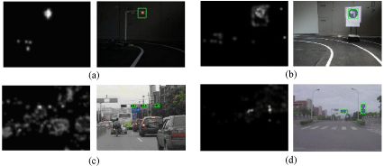
I(δ) is the intensity of pixel δ. IT1 is the corresponding intensity threshold in procedure 1), and IT2 is the corresponding intensity threshold in procedure 3). Nlight is the total number of traffic light, and NT1 is the upper limit of Nlight. Nwhite is the number of highlight pixels and NT2 is the corresponding threshold of Nwhite in procedure 3). The detection results of both traffic light and traffic sign in micro scale environment and actual traffic environment are shown as figure 6 (Figure 6).
Figure 6: Traffic light and traffic sign detection result, (a) and (b) are in micro traffic environment, (c) and (d) are in actual traffic environment, with CSM image (left) and detection result (right).
Improved spatial-bag-of-features for recognition
Traffic sign detection method is similar to the procedure of traffic light detection mentioned above. After the ROI is located, a histogram matching approach based on improved spatial-bag-of-features is proposed, which could ensure the requirements of real-time and robust [16]. This method contains two kinds of histogram bag-of-features, linear projection histogram and circular projection histogram. And after the processes of equalization, zero-suppression and sorting to each histogram, the final result is invariable under translation, scale and rotation, which is different from ordinary histogram matching method and very adaptable to different environment.
The linear projection histogram of spatial-bag-of-features is defined as followed.
HΘ = [hΘ(1),hΘ(2),…,hΘ(m)] (10)
Θ = [(L1, θ1),(L2, θ2),…,(Lm, θm)] (11)
HΘ is the bag of linear projection histograms, which contains m sub-histograms; Θ is the parameter vector of m-dimensional linear projection. Θ(i) stands for the parameter (Li ,θi) of the ith linear projection histogram. LiM is the interval divide number of histogram, and θi is the angle of linear projection.
The circular projection histogram of spatial-bag-of-features is defined as followed.
H λ=[hλ(1),hλ(2),…,hλ(n)] (12)
λ=[(L1,x1,y1),(L2,x2,y2),…,(Ln,xn,yn)] (13)
Hλ is the bag of circular projection histograms, which contains n sub-histograms; λ is the parameter vector of n-dimensional circular projection. λ(i) stands for the parameter (Li,xi,yi) of the ith circular projection histogram. Li is the interval divide number of histogram, and (xi,yi) is origin position of circular projection. The rotation angle ε can be obtained by compare the circular projection histogram between template and target.
In order to reduce the impact from the histogram interval division, to which the matching procedure is very susceptible, an improved sorting rule based on spatial-bag-of-features is proposed. The center of gravity along the projection direction of each histogram is used as the rule of sorting instead of the statistics value. The center of gravity of histogram is defined as equation (14).
Cosine similarity and correlation similarity are combined here to judge the relevance between the detected sign and the template, which is defined equation (15) and (16). ?i is the weight of each histogram.
The procedure of traffic sign recognition contains the following steps.
- Resize ROI S1 and form S2 to keep the same size as template T.
- Apply inner contour detection to S2, and then get S3 through minimum bounding rectangle.
- Binarize S3 by OTSU algorithm and get S4.
- Using circular projection histogram statistics and ordered bag-of-features to S4 and template T, gain the rotation angle ε of the origin image.
- Apply linear projection along the rotation angle ε, and the following directions to rotation angle: parallel to ε, vertical to ε, and 45degrees to ε. Then use equalization, zero-suppression, and improved ordered bag-of-features to the result projection histograms.
- Calculate the cosine similarity and correlation similarity between the image and the template, thus get the final result of recognition.
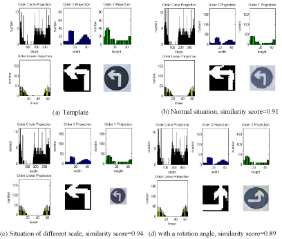
The projection histogram and the similarity score of traffic sign recognition with different distance and different direction to the template is shown in figure 7 (Figure 7). Operating time of traffic sign recognition is shown in Table I.
Figure 7: Results of traffic sign recognition. Instructions of each figure: circular projection histogram (upper left), parallel linear projection histogram (upper middle), vertical linear projection histogram (upper right), 45degree linear projection histogram (lower left), binarized image (lower middle), and ROI of original image (lower right).
    Traffic light
    Average operating time (ms)


    Traffic sign    image pretreatment
    9.2


    Traffic sign    CSM generation
    38.9


    Traffic sign    recognition
    20.1
Table I: Average operating time of traffic sign recognition.
Experimental Results
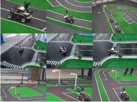
The detail configuration of MicroIV is given as followed. In the first layer of hardware framework, the micro controller is a 16-bit MCU, connected with an Omron E6A2-CW3C speed encoder, and several infrared sensors around the vehicle. In the second layer, the configuration of the single-board computer is AMD G-T56N 1.6GHz with 2G RAM. The camera deployed here is Logitech C170 webcam. The communication between the two layers is realized by RS232 serial port at the baud rate of 115200. The recognition statistics of different autonomous driving functions in different speed are shown in Table II. Figure 8 is captured images of experiments in different scenarios (Figure 8).
Figure 8: Captured images of experiments.
    Recall (%)
    Speed (m/s)


    Lane Keep    Driving
    96.4
    1


    Collision    Avoidance
    92.3
    0.8


    Intersection    Driving
    83.3
    0.5


    Autonomous    Parking
    87.5
    0.3
Table II: Recognition statistics.
Conclusion
In this paper, a reliable and reasonable framework of MicroIV including both software and hardware architectures is proposed, which satisfies the requirements of stable, cost-effective and expandable. The framework is capable of multi-tasks in autonomous driving like lane-keeping, collision avoidance, autonomous parking and so on. A global path planning and navigation method based on time division based hierarchical topology maps is proposed to simulate actual traffic environment with time varying rules of intersections. And the environmental perception approach for traffic light and traffic sign recognition based on VSA is presented to locate ROI more efficiently, as well as an improved spatial-bag-of-features based method to make the recognition more adaptable and robust. As a consequence, the MicroIV is qualified with traffic flow simulation. The multi-vehicles collaboration and cooperative system will be further discussed based on MicroIV.
Acknowledgment
This work was funded by the Major Research Plan of National Natural Science Foundation (91120018) and the General Program of National Natural Science Foundation of China (61174178/51178268).
References
- Sugiyama Y, Fukui M, Kikuchi M, Hasebe K, Nakayama A, Nishinari K, et al. Traffic jams without bottlenecks—experimental evidence for the physical mechanism of the formation of a jam. New Journal of Physics. 2008; 10: 033001.
- Yang M, Wan N, Wang B, wang C, Xie J. CyberTORCS: An Intelligent Vehicles Simulation Platform for Cooperative Driving. International Journal of Computational Intelligence Systems. 2011; 4: 378-385.
- Boxill S A, Yu L. An Evaluation of Traffic Simulation Models for Supporting ITS [M]. Houston. 2000.
- Soetedjo A, Yamada K. Fast and robust traffic sign detection. Systems, Man and Cybernetics, 2005 IEEE International Conference on. IEEE. 2005; 2: 1341-1346.
- Gao X W, Podladchikova L, Shaposhnikov D. Recognition of traffic signs based on their colour and shape features extracted using human vision models. Journal of Visual Communication and Image Representation. 2006; 17: 675-685.
- Wang Y, Shi M, Wu T. A method of fast and robust for traffic sign recognition. Image and Graphics. ICIG'09. Fifth International Conference on. IEEE. 2009: 891-895.
- Miura J, Kanda T, Shirai Y. An active vision system for real-time traffic sign recognition. Intelligent Transportation Systems, 2000. Proceedings. IEEE. 2000: 52-57.
- Yang L, Meer P, Foran DJ. Multiple Class Segmentation Using a Unified Framework over Mean-Shift Patches. Proc IEEE Comput Soc Conf Comput Vis Pattern Recognit. 2007; 2007: 1-8.
- Itti L, Koch C. Feature combination strategies for saliency-based visual attention systems. Journal of Electronic Imaging. 2001; 10: 161-169.
- Zhang Q, Gu G, Xiao H. Computational mode of visual selection attention. ROBOT. 2009; 6: 574-580.
- Navalpakkam V, Itti L. An integrated model of top-down and bottom-up attention for optimizing detection speed. Computer Vision and Pattern Recognition. IEEE Computer Society Conference on. IEEE. 2006; 2: 2049-2056.
- Won W J, Ban S W, Lee M. Real time implementation of a selective attention model for the intelligent robot with autonomous mental development. Industrial Electronics. Proceedings of the IEEE International Symposium on. IEEE. 2005; 3: 1309-1314.
- Ye X, Lei Y, Hou H. Design of intelligent mobile vehicle system and its global optimal path planning. Proc. ICIT. Industrial Technology. 2008; 1-5.
- Sariff N, Buniyamin N. An overview of autonomous mobile robot path planning algorithms. Research and Development. SCOReD 2006. 4th Student Conference on. IEEE. 2006: 183-188.
- Liang S, Xiong C. Tracking moving vehicle based on mean shift algorithm. ICISE. 2009; 1499-1502.
- Cao Y, Wang C, Li Z. Spatial-bag-of-features. Computer Vision and Pattern Recognition (CVPR). IEEE Conference on. IEEE. 2010: 3352-3359.
