
Research Article
Adv Res Text Eng. 2024; 9(1): 1096.
Design and Development of Composites Walking Stick Using Filament Winding Process: Analytical, Experimental & Numerical Analysis
Sameer Kumar Behera¹; Singh SP²; Behera BK³*
1School of Interdisciplinary Research, Indian Institute of Technology Delhi, India
2Department of Mechanical Engineering, Indian Institute of Technology Delhi, India
3Department of Textile and Fibre Engineering, Indian Institute of Technology Delhi, India
*Corresponding author: Behera BK Department of Textile and Fibre Engineering, Indian Institute of Technology Delhi, India. Email: behera@Textile.iitd.ac.in
Received: January 11, 2024 Accepted: February 19, 2024 Published: February 26, 2024
Abstract
This study aims to design and develop a walking stick made of composite materials using the filament winding method. The composite material chosen for its lightweight and superior specific strength is widely utilized in industrial applications as an alternative to steel. The filament winding process is selected in this study due to its ability to fabricate symmetric objects. In comparison to the hand lay-up approach used in composite manufacturing, filament winding technology is a continuous fabrication technique that offers high levels of automation, reproducibility, and cost-effectiveness. One of the key advantages of using the filament winding process, particularly when compared to conventional metal-designed structures such as pipes, pressure vessels, and rocket engine cases, is its capability to produce designs with exceptional stiffness-to-weight ratios, high fiber volume fraction, and strength-to-weight ratios.
In this study, analytical methods, initially implemented through MATLAB code, are employed to predict the critical load of the walking stick. The results highlight the superior performance of the composite material in terms of critical load. Subsequently, the filament winding method is utilized to fabricate the composite structure of the walking stick, incorporating continuous fibers, such as glass and sisal, in a specific pattern around a mandrel. The walking stick undergoes testing to examine its mechanical properties, including stiffness and strength, and the results are exploited to optimize the design and fabrication process. The findings indicate that the composite walking stick, manufactured using filament winding, demonstrates higher flexural strength compared to conventional walking sticks. Furthermore, finite element methods are utilized to validate the experimental results by performing simulations in LS-DYNA. This is done to predict the flexural strength of the glass and sisal composite in the walking stick. The observation reveals a close match between the simulation data and experimental results, affirming the accuracy of the Finite Element Method (FEM) model in predicting the performance of the composite walking stick.
Keywords: Filament winding process; Walking Stick; Composite; Three-point bending Test
Introduction
Walking sticks are essential mobility aids, significantly improving the lives of a substantial portion of the global population. The World Health Organization (WHO) reported in 2011 that around 10% of the world's population faces mobility challenges or disabilities. For these individuals, walking sticks are indispensable tools. These aids offer a multitude of benefits, including enhanced balance, reduced joint discomfort, and increased stability. By using a walking stick, those with mobility limitations can move with greater ease and confidence, leading to a substantial improvement in their overall well-being. In recent years, the senior population's percentage and absolute size have increased. Many diseases are on the rise as a result of our ageing population and technological comforts. The expenses caused by the illness also significantly impact the least developed countries.
Walking sticks have evolved over time and are now available in a wide variety of styles, materials, and lengths. It can be made from various materials such as wood, metal, glass fibre, carbon fiber, and sisal fibre composite materials. Composite materials are increasingly being used to make walking sticks due to their high strength-to-weight ratio and durability [1]. Composite materials combine two or more materials with different physical and chemical properties to create a material with superior characteristics. The most common types of composite materials used in walking sticks are carbon fiber, glass fibre and natural fibre. There are many processes to fabricate a composite walking stick i.e pultrusion, hand layup and filament wainding process. However, in pultrision and hand layup process have very poor strength due to the delamination, it leads to a limitation of their applications in structural parts with complex shapes. In order to overcome this limitation, textile reinforced composite structures have been studied. In comparison to the hand lay-up and pultrusions approach, filament winding technology is a continuous fabrication technique that can be highly automated, reproducible, and very inexpensive [2]. It is a process that involves wrapping continuous fibers around a mandrel in a specific pattern to create a composite material [3] as shown in Figure 1. It is an efficient and effective method for producing high-quality composite walking sticks that are strong, lightweight, durable, and customizable.
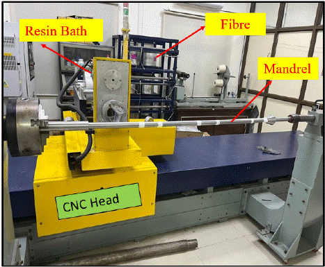
Figure 1: CNC Machine of Filament winding Process.
Very few studies have been conducted on walking sticks, and some researchers have proposed the idea of utilizing local materials such as Rhizophora wood to design walking sticks for the elderly due to their strength and durability [4]. In addition, certain researchers have designed smart sticks to assist the visually impaired both indoors and outdoors by incorporating ultrasonic sensors. These efforts have also involved the development of composite walking sticks [5,6]. Surprisingly, there is a lack of comprehensive research on walking sticks, particularly those made through the filament winding process. Furthermore, no studies have reported on the mechanical behaviour of composite walking sticks or investigated into the numerical modeling of walking sticks.
The primary focus of this research is to design and fabricate walking sticks using composites through the filament winding process. To achieve optimal material selection and fiber orientation, the study incorporates critical load analysis conducted through analytical calculations on the MATLAB platform. Additionally, a three-point bending test is performed on the composite walking sticks using a Universal Testing Machine (UTM). The objective is to evaluate the mechanical behavior and performance of the walking sticks under applied loads. Moreover, finite element modeling of the three-point bending is carried out using the LS-DYNA platform. This computational approach aids in simulating and analyzing the structural response of the walking sticks, allowing for a comprehensive understanding of their mechanical characteristics. The integration of analytical calculations, experimental testing, and numerical simulations ensures a thorough investigation of the walking sticks' structural integrity and performance. The multi-faceted approach provides valuable insights for optimizing the design and fabrication process, contributing to the development of robust and efficient composite walking sticks with enhanced mechanical properties.
Materials and Methods
The fabrication process of a walking stick is a comprehensive endeavor that involves several materials and sophisticated design and manufacturing techniques. The key materials involved in this process include glass, sisal, epoxy, steel, thin aluminum sheets, and wax.
First and foremost, the mandrel, which serves as the core structure of the walking stick, was meticulously designed using Solid works software. The dimensions of the mandrel were specified, with a length of 1200mm and a diameter of 30 mm. Additionally, a handle for the walking stick was designed with a 40 mm diameter, as indicated in Figure 2. This step is crucial as it defines the final shape and size of the walking stick, ensuring it meets the desired specifications.
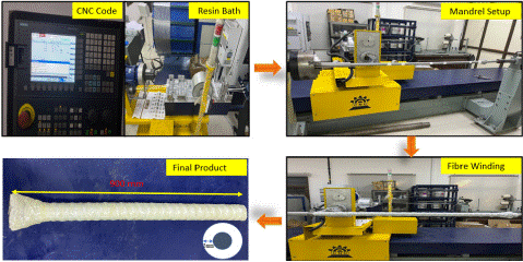
Figure 2: Process of fabricate walking stick.
The next stage in the fabrication process involved the physical creation of the mandrel, a task undertaken at the IIT Delhi central workshop. Skilled technicians and specialized machinery at the workshop were responsible for fabricated the mandrel with precision, ensuring it matched the design specifications down to the last detail.
With the mandrel now prepared, the focus shifted to the design of the walking stick itself. Cad Fill software was employed to create a detailed design, and this software also played a critical role in generating the CNC (Computer Numerical Control) code required for the subsequent manufacturing steps. The CNC code serves as a set of precise instructions, guiding the CNC machine in shaping and finishing the walking stick according to the predetermined design parameters. The CNC code was then imported into a filament winding machine, a piece of equipment that plays a pivotal role in the fabrication process. This machine follows the instructions within the CNC code, meticulously directing the placement of glass, sisal fibers, and epoxy. The winding machine ensures that the composite materials are laid down in a specific pattern and orientation, following an intricate path. This process is essential in creating a lightweight but incredibly robust composite structure, making the walking stick both reliable and durable.
To secure the composite materials, epoxy resin was used as a binding agent. The ratio of fibers to epoxy was maintained at 60:40, with the angle of 55 degrees used for fabriction the composite. This particular angle was chosen as it is known to provide the composite with high strength, a crucial characteristic for a walking stick.
Exprimental
In the conducted three-point bending test on a composite walking stick, a Zwick Roell Z250 Universal Testing Machine (UTM) was employed for precise material characterization. The initial step involved meticulous calibration of the UTM to ensure accurate and reliable results. The walking stick, fabricated from a composite material, was then securely mounted horizontally on the supports. Care was taken to align it centrally under the loading head, and the support anvils were symmetrically positioned, adhering to the specified span length. The load cell of the UTM was carefully zeroed, and the testing parameters were set, including the desired test speed, which was established at a controlled rate of 5 mm/min. Furthermore, the data acquisition system was configured to capture detailed load and deflection measurements throughout the experiment. Before initiating the test, the initial span length of the walking stick was measured, providing a baseline for subsequent analysis. Additionally, an extensometer was attached to the composite material to enable precise strain measurement. The three-point bending test commenced by applying a vertical load to the walking stick, simulating real-world loading conditions. The UTM seamlessly recorded load and deflection data continuously, offering a comprehensive dataset for subsequent analysis. The test was meticulously monitored to ensure the controlled application of force, avoiding any sudden or excessive loading that could compromise the integrity of the walking stick. Post-test, the acquired data was analysed to generate a load-displacement curve, which served as the basis for determining essential mechanical properties of the composite material. The thickness and width of the composite samples, measured using a micrometer with an accuracy of +- 1% before testing, provided critical information for a comprehensive understanding of the material's behavior. The samples were cut in accordance with ASTM standards, with dimensions specified at 160mm in length and 30mm in diameter, as illustrated in the Figure 3.
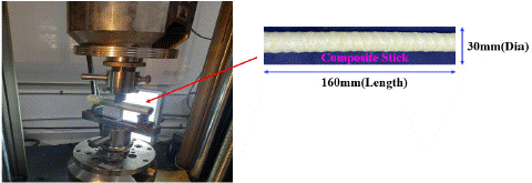
Figure 3: Three point bending test on composite walking stick.
Analytical Modelling using MATLAB code
Analytically modeling the critical load on a walking stick involves assessing the maximum force it can support before buckling or failing, as shown in figure. To do this, it considers the stick as a slender column with a certain length, diameter, and material properties. Euler's buckling formula is used to calculate the critical load based on the stick's modulus of elasticity, moment of inertia, and effective length. The moment of inertia depends on the stick's cross-sectional shape, typically cylindrical, and the effective length is determined by the support conditions at the stick's ends. By plugging these values into the formula, we can find the critical load. Applying a safety factor is also advisable to account for real-world variations and ensure the walking stick can withstand the expected loads. This analytical approach provides a theoretical estimate of the stick's performance, but real-world factors and manufacturing imperfections may necessitate additional testing or more advanced analyses for precise results.Assume that the walking stick is a straight, slender column with a constant cross-section. Neglect any external factors like hand pressure and consider only the axial loading on the stick. Apply Euler's formula [4] for buckling to determine the critical load (P_critical) for a slender column
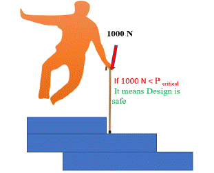
Figure 4: The full body load on the stick.
P_critical = (p^2 EI)/(K^2 L^2 ) (1)
where:
E is the modulus of elasticity of the material.
I is the moment of inertia of the cross-sectional shape.
K is the effective length factor, which depends on the boundary conditions (fixed, pinned, or free).
L is the effective length of the walking stick.
Above formula is used to determine the load using MATLAB coding,it is due to variation of parameter, the matlab code is shown in appendix 1.
Numerical model of Walking Stick
The Computer Aided Model (CAD) model of the walking composite stick was created using SolidWorks and subsequently exported to LS-DYNA software for performed a three-point bending analysis of composite walking stick, The materials for walking stick was modeled using solid element in the type of MAT_PIECEWISE_LINEAR_PLASTICITY [4] (MAT 024). The material property of the glass and sisal is derived from experimental test and then stress vs starin diagram is incorporated in the Materials Model. The supports and the loading roller were modeled by shell element, using rigid material model (MAT_020/MAT_RIGID). These were assigned with rigid material model because it undergoes no deformation in comparison with the composite walking stick, produced by filament wainding technique. The boundry conditions are, both supports were fixed, and a prescribed displacement was applied to the loading roller, as illustrated in Figure 5. To enhance the simulation's realism, surface-to-surface contact modeling was incorporated between the rolling surface of the loading roller and the corresponding surface of the walking composite stick. Frictional contact was taken into consideration to model the interaction between the composite walking stick and the supports, as well as the loading roller. This comprehensive approach aimed to capture the intricate behavior of the walking composite stick under three-point bending conditions.
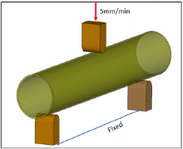
Figure 5: Three point bending test on Composite stick.
Results and Discussions
The critical load of the walking stick was calculated using Euler's formula, and the results, as depicted in Figure 6, revealed a noteworthy trend. It was observed that the critical load increased proportionally with the thickness of the stick. Notably, the critical load was found to be dependent on the Young's modulus of the materials employed. Glass, with its significantly higher modulus compared to wood, emerged as a more robust option. This finding gained significance when the walking stick, constructed from wood, the stick broke easily under just 1000 N of force. In response to these findings, the decision was made to fabricate a walking stick using glass and sisal materials in the filament winding process.
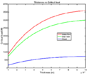
Figure 6: Critical load V/s Thickenss of composite walking stick for different materials.
A subsequent 3-point bending test, illustrated in Figure 7, was conducted to determine the bending strength of the composite material. For thr finding of bending strength, different winding angle is used in the process, two walking sticks were fabricated with hoop winding, with glass and sisal fibers and one with glass wound at a 45-degree angle. The force versus deformation results from the 3-point bending test unveiled compelling insights. The glass fiber stick, wound in a hoop configuration, indicate a maximum force of 3100 N. In contrast, the sisal fiber hoop-wound stick exhibited a significantly lower force value of 1400 N, as shown in Figure 9. This discrepancy was attributed to the distinct tensile and compressive properties inherent in the chosen materials.
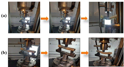
Figure 7: Deformation behaviour for Hoop wound of (a) glass and (b)sisal composite stick.
Furthermore winding glass fibers at a 45-degree angle to exploit their superior bending strength, as corroborated by literature [7]. The resulting bending strength of the glass hoop-wound stick, sisal hoop-wound stick, and the stick wound at a 45-degree angle with glass fibers are graphically presented at Figure 10. The results clearly showed that the stick with a 45-degree angle wound with glass fibers was stronger than the others. This superiority is due to the interlacing of fibers at this specific angle, facilitating their collective participation in resisting the applied load. Moreover, the interlaced fibers exhibited excellent cohesion, further enhancing the overall strength of the composite material. Further numerical modeling was conducted to validate experimental data for a walking stick. It was observed that the maximum force for a glass fiber composite stick wound in a hoop configuration was 3300 N, while for a sisal fiber composite stick, it was 1500 N. The maximum force value for a stick wound at a 45-degree angle with glass fibers composite was found to be 3600 N, as shown in the figure. After obtaining the numerical data, a comparison with the experimental data was performed for validation, revealing a match between the numerical and experimental results.
During the three-point bending tests of composite walking sticks, failure surfaces were observed as depicted in Figures 7 and 8. In the case of hoop winding with glass and sisal composite sticks, the maximum crack initiation occurred within the sticks. However, for the 45-degree glass-wound stick, the crack manifested in the outer layer of the stick under loading conditions. The failure transpired at the moment of reaching the critical stress state in the material, leading to the emergence of a critical crack with unstable growth. The location of the critical crack is associated with fiber/matrix debonding, after which the fibers underwent cracking.
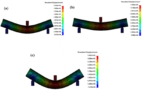
Figure 8: FEM Deformation behaviour of (a) hoop sisal , (b) hoop glass and (c) 45 degree wound glass composite stick.
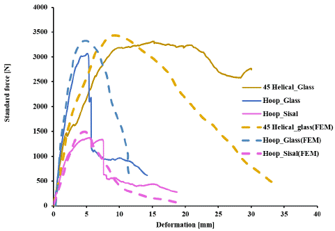
Figure 9: Force V/s Displacement curve of Three point Bending Test( Exp. & FEA.)
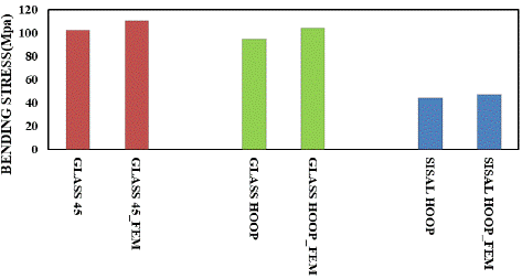
Figure 10: Bending strength comprasion ( Experiment V/s FEA).
This detailed study highlighted how important it is to pick the right materials for making a walking stick and how the way it's made affects how well it works. By using materials like glass and sisal and wrapping them in a certain way, the walking stick becomes stronger and can handle more weight. The 3-point bending test, helped us figure out how strong the walking stick is when it bends. This information is useful for making better-designed walking sticks in the future.
Conclusions
In this study, a comprehensive approach was undertaken to assess the flexural strength and critical carrying capacity of composite wound sticks. This complex investigation involved analytical methods, Finite Element Analysis (FEA) simulations, and experimental tests, collectively aimed at providing a thorough understanding of the structural behaviour and load-bearing capabilities of the composite wound sticks.
• The results indicate that the composite walking stick made of sisal and glass has a higher critical load capacity compared to wood.
• Comparison between the simulation and experimental data showed that the contact force obtained from the numerical results agrees well with the experimental data.
• The helically-wound (45 degree) composite stick has a higher flexural strength than other sticks.
Author Statements
Declaration of Conflicting Interests
The authors declared no potential conflicts of interest with respect to the authorship, research and publication of this article.
References
- Introduction to Composite Materials. 2010.
- Balasubramanian K, Sultan MTH, Rajeswari N. 4 - Manufacturing techniques of composites for aerospace applications. In: Jawaid M, Thariq M, Eds. in W, editors. Sustainable Composites for Aerospace Applications. Woodhead Publishing. 2018; 55–67.
- Guo K. Design of winding pattern of filament-wound composite pressure vessel with unequal openings based on non-geodesics. J Eng Fibers Fabr. 2020; 15: 1558925020933976.
- Maxfield B. Chapter 3 - Simple Functions. In: Math BM, editor. Essential Mathcad for Engineering, Science. Boston: Academic Press. 2009; 53–69.
- Gunaryo K, Heriana H, Sitompul MR, Kuswoyo A, Hadi BK. Experimentation and numerical modeling on the response of woven glass/epoxy composite plate under blast impact loading. Int J Mech Mater Eng. 2020; 15: 4.
- Betelie AA. Mechanical properties of sisal-epoxy composites as functions of fiber-to-epoxy ratio. AIMS Mater Sci. 2019; 6: 985-996.
- Li X, Wang L-G, Zhang Y-S, Zhang N. Flexural behaviour of hollow reinforced concrete-filled fibreglass tubular beams. Proc Inst Civ Eng - Struct Build. 2022; 1-17.