
Research Article
Ann J Materials Sci Eng. 2015;2(1): 1017.
Localized Effects in Periodic Elastoplastic Composites
Jacob Aboudi* and Michael Ryvkin
Department of Engineering, Tel Aviv University, Israel
*Corresponding author: Jacob Aboudi, Department of Engineering, School of Mechanical Engineering, Tel Aviv University, Ramat Aviv 69978, Israel
Received: November 24, 2014; Accepted: February 14,2014; Published: February 18, 2015
Abstract
A method is applied for the study of the field distributions in metal matrix fiber reinforced composites with periodic microstructure in which localized damage exists in the form of complete or partial fiber loss and crack. In addition, the behavior of ceramic/metal periodically layered composites with a single broken ceramic layer is determined. The pro-posed analysis is based on continuum damage mechanics considerations, and the method of solution combines three distinct approaches. In the first one, referred to as the representative cell method, the periodic composite domain is reduced, in conjunction with the discrete Fourier transform to a finite domain problem of a single representative cell. This method has been previously applied on linear thermoelastic, smart and electrostrictive composites, but is presently extended and applied on elastoplastic composites (presently deformation and incremental plasticity). In the second approach, the appropriate far-field boundary conditions in the transform domain are applied in conjunction with the high-fidelity generalized method of cells micromechanical model for the prediction of the macroscopic behavior of the inelastic composite. The third approach consists of the application of the inelastic higher-order theory for the computation of the elastoplastic field in the transform domain. An inverse transform provides the actual field. The effect of damage is included in the analysis in the form of eigenstresses which are a priori unknown. Hence an iterative procedure is employed to obtain a convergent solution.
The proposed method is verified by a comparison with an analytical solution, and several applications illustrate the applicability of the method for metal matrix composites with localized damage in the form of a crack or fiber loss.
Keywords: Localized damage; Cracked fiber reinforced materials; Representative cell method; High-Fidelity generalized method of cells; Inelastic higher-order theory; Elastoplastic composites
Introduction
The micromechanical analysis of composites with periodic microstructure is usually carried out by identifying and analyzing a repeating unit cell. However, when localized effects such as one or several cracks occur in the composite, the periodicity is lost and its behavior cannot be determined directly by analyzing a repeating unit cell. If these effects are nevertheless included in the analysis of the repeating unit cell, the resulting behavior would correspond to that of a composite with periodic (i.e., not localized) effects which obviously is an unrealistic situation.
In a recent article, Aboudi and Ryvkin [1] proposed the analysis of linearly elastic composites with localized damage by representing the effect of the latter by eigenstresses. This analysis combines continuum damage mechanics considerations with three different approaches. In the first one the idea of using the eigenstresses to represent the nonlinear effects enables application of the representative cell method, Ryvkin and Nuller [2], based on the discrete Fourier transform which is applicable to linear problems. As a result the initial problem formulated for a domain comprising a large number of cells is reduced to a problem for a single representative cell. Appropriate far-field boundary conditions (which are not influenced by the localized effects) in the transform domain are applied in conjunction with the highfidelity generalized method of cells (HFGMC) [3]) micromechanical model which forms the second approach. The third approach consists of the application of the higher-order inelastic theory, Aboudi et al. [4], for the computation of the field in the transform domain. An inverse transform provides the actual field. The effect of damage is included in the analysis in the form of eigenstresses which are a priori unknown. In Ryvkin and Aboudi [5], this approach has been also proven to be successful and effective in the analysis of cracked layered elastic composites, where one or several combinations of a transverse and two longitudinal cracks (H-cracks) caused branching have been investigated. Furthermore, it has been successfully applied for the prediction of the field distributions in electro-magneto-thermoelastic composites with cracks, cavities and inclusions, Aboudi [6]. A brief review of various methods for the analysis of localized effects in thermoelastic composites has been recently presented by Aboudi and Ryvkin [3].
Thus far, the representative cell method has been employed in the analysis of linearly thermoelastic [1], electro-magneto-thermo-elastic [6] and electrostrictive (nonlinear) [7] composites. In the present investigation, this method is extended to elastoplastic materials (presently incremental and deformation elastoplasticity). In addition, the approach of Aboudi and Ryvkin [1] in analyzing localized damage in composites is presently further extended to enable the prediction of the behavior of elastoplastic periodic composites which include localized damage in the form of a cavity (a fiber loss) or a crack. In this approach, the plasticity effects are represented in the form of eigenstresses which extend over the entire considered region. In addition, these eigenstresses include the effects of localized damage which are operative over the damaged region only as has been proposed by Aboudi and Ryvkin [1] in the case of linear elasticity. Thus, according to our present proposed approach these eigenstresses include the combined contributions of the effects of plasticity as well as the localized damage. These eigenstresses are not known in advance and, therefore, an iterative procedure is employed to establish a convergent solution.
This article is organized as follows. In the next section the problem is formulated which followed by the method of solution section. The verification of the method is performed by a comparison with analytical solution for an infinite elastoplastic (deformation plasticity) medium with embedded cavity subjected to a remote biaxial loading, Ishikawa [8]. The application section presents the applicability of the proposed method for the prediction of the behavior of elastoplastic solids with embedded cavity, fiber reinforced metal matrix composites with a complete and partial fiber loss, and layered metal matrix composite with a single broken layer. The final section presents the conclusions and several possible future generalizations.
Problem Statement
The present investigation deals with elastoplastic composites that possess a periodic microstructure and include a localized damage such as a crack, fiber loss or cavity. This type of composites is illustrated in Figure 1(a) where the fibers, oriented in the x1-direction and arranged in a doubly periodic manner, are embedded in an elastoplastic material.
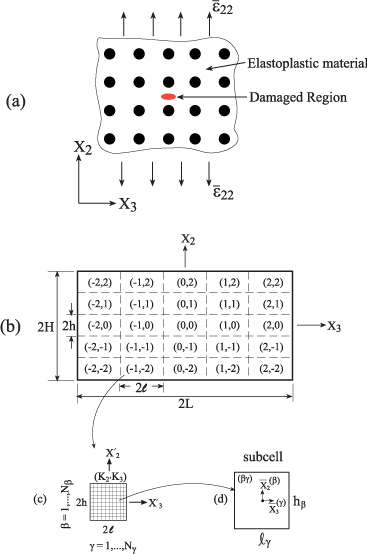
Figure 1: (a) A doubly periodic unidirectional fiber reinforced composite
with a localized damage, is subjected to a remote strain
at infinity. (b) A
rectangular domain 2H × 2L of the composite is divided into repeating cells.
These cells are labeled by (K2, K3) with -M2 = K2 = M2 and -M3 = K3 = M3,
and the size of every one of which is 2h × 2l (the figure is shown for M2 =
M3 = 2). (c) A characteristic cell (K2, K2) in which local coordinates
are introduced whose origin is located at the center. It is divided into Nβ × Nγ
subcells (the figure is shown for Nβ = Nγ = 10). (d) Subcell (βγ).
The response of the considered composite is determined by satisfying the equilibrium equations in every one of its constituents, namely:
∇ . σ = 0 (1)
in the absence of body forces, where σ is the stress tensor. In addition, the interfacial conditions that requires in the case of perfect bonding the continuity of displacements u and tractions t between the fibers (f) and matrix (m) constituents must be imposed:
uf = um, tf = tm (2)
In the present investigation elastoplastic materials are considered whose constitutive equations are given (assuming isothermal conditions) by
σ = C: (Σ - ΣP) (3)
where C is the stiffness tensor of the material, and Σand ΣP are the strain and plastic strain tensors, respectively. In the framework of classical plasticity, the evolution law of the plastic strain ΣP is governed by the Prandtl-Reuss equations, c.f. Mendelson [9]:
ΔΣP = Δλ s (4)
where Δλ is the Prandtl-Reuss proportionality function and s is the deviator tensor of σ.
In Aboudi and Ryvkin [1], the effect of localized damage in perfectly elastic composites was represented by eigenstresses as follows. The constitutive equations of elastic material in the presence of damage are determined by the principle of strain equivalence Lemaitre and Desmorat [10], according to which the strains in the damaged and effective configurations are equal. This implies that
σ = C: Σ - σe (5)
where σe is eigenstress which has the form
σe = DC: Σ (6)
where D is the damage variable which is equal to zero in the undamaged constituents, whereas D = 1 in cracks and cavity regions thus representing a complete damage. In addition to the contribution of Aboudi and Ryvkin [1] where this method was presented and applied to investigate localized damage in elastic composites, this approach has been also shown to be successful in the modeling of an H-crack (a transverse crack accompanied by two longitudinal ones) in ceramic matrix composites Ryvkin and Aboudi [5], and cracks, cavities and inclusions in electro-magneto-elastic composites Aboudi [6].
In the present paper where the constitutive equations of the phases incorporate inelastic effects we propose to continue representing the constitutive equations by Equation (5) but generalize Equation (6) as follows
σe = DC: Σ + (1-D)C: ΣP (7)
Thus, the eigenstresses presently include the plasticity effects in addition to the damage. It should be noted that in the absence of damage (D = 0) the plasticity effects are included in the analysis in the form of eigenstresses and their effects extend over the entire region. In the presence of damage in certain localized regions (0 < D < 1) further terms are added to the latter. In regions with complete damage (D = 1) where cracks and cavities are simulated, the plasticity effects as expected are absent. It can be readily observed that with introduction of the damage parameter D, it is possible to model a region whose behavior is elastoplastic everywhere except for one or more localized domains where D = 1 which corresponds to cavities and cracks. Evolving damage, stiff and soft inclusions, where D takes suitable values between zero and one have been utilized in the modeling of thermoelastic, electro-magneto-thermo-elastic and electrostrictive composites, see Aboudi and Ryvkin [1], Aboudi [6] and Aboudi [7], respectively.
Finally, as it is discussed in the next section, the far-field boundary conditions that are applied on the composite should be incorporated.
Method of Solution
Far away from the region with localized damage, the periodic elastoplastic composite is governed at any instant of loading by its macroscopic (global) behavior. The constitutive equations that model this behavior can be micromechanically established by the HFGMC model, Aboudi et al. [4] chapter 6, and are given by
where C* is the effective stiffness tensor and , and are the global stress, total strain and plastic strain tensors, respectively.
Let us consider a rectangular domain -H = x2 = H, -L = x3 = L of the composite which includes the damaged region. Although this region includes the localized damage, it is assumed that it is extensive enough such that the inelastic stress, strain and displacement fields at its boundaries are not influenced by the damage existence and therefore, the macroscopic constitutive equations (8) are applicable. Consequently, the boundary conditions that are applied on x2 = ± H and x3 = ± L are referred to as the far-field boundary conditions. According to the representative cell method, Ryvkin and Nuller [2], this region is divided into (2M2 + 1) × (2M3 + 1) identical cells, see Figure 1(b) which is schematically shown for M2 = M3= 2 cells. Every cell is labeled by (K2, K3) with K2 = -M2, …, M2 and K3 = -M3, …, M3. In each cell, local coordinates (x’2, x’3) are introduced whose origins are located at its center, see Figure 1(c) which shows the representative cell that is schematically divided into Nβ= 10 and Nγ = 10 subcells.
The equilibrium equation (1) of the materials within the cell (K2, K3) takes the form
The constitutive equation in the cell, Equation (5), can be written as
where the eigenstresses in cell (K2, K3) are given according to Equation (6) by
and
and 0 < D < 1 for a partial damage.
The continuity of displacements u(K2,K3) and tractions t(K2,K3) between adjacent cells should be imposed. Thus,
where K2 = -M2,…, M2 - 1, K3 = - M3,…, M3 - l = x’3= l, and
where K2 = -M2, …, M2, K3 = -M3, …, M3 - 1, -h = x’2 = h. Here t(j) is the traction vector acting at a boundary perpendicular to the xj -axis, j = 2, 3.
In the following, the appropriate form of the far-field boundary conditions that specify the tractions and displacements at the opposite sides x2 = ±H, x3 = ±L of the rectangle of Figure 1(b) are presented. The tractions at the opposite sides of the rectangular domain are equal:
The displacements at the opposite sides, on the other hand, differ by certain jumps as follows
where σ2 and σ3 denote the vectors of the far-field displacement differences whose components are given by
and are the macroscopic (global) strains of the unperturbed periodic composite which have to be determined from Equation (8) for a given type of applied loading. Suppose, for example, that the composite is subjected to a transverse strain loading in all other directions. The macroscopic equations (8) that describe the (undamaged) composite’s behavior are utilized to determine the remaining average strains to be employed in Equation (21).
The double finite discrete Fourier transform of the displacement vector u(K2 ,K3 ) , for example, is defined by
where
The application of this transform to the boundary value problem (9)-(20) for the rectangular domain -H < x2 < H, -L < x3 < L, divided into (2M2 + 1) × (2M3 + 1) cells, converts it to the problem for the single representative cell -h < x’2 < h, -l < x’3 < l with respect to the complex valued transforms. The field equations obtained from the equilibrium and constitutive equations have the form
and
where the transformed eigenstress tensor is given by
The conditions relating the opposite boundaries of the representative cell in the elastic problem case were derived by Aboudi and Ryvkin [1]. Following their approach one obtains from (13)-(20)
where p = -M2, …, M2; q = -M3, …, M3. In these equations, σp,q denotes the Kronecker delta.
The representative cell boundary value problem (23)-(29) have been solved by employing the inelastic higher-order theory, Aboudi et al. (2013), chapter 11. According to this theory, the domain -h = x’2 = h, -l = x’3 = l (the representative cell) is divided into Nβ × Nγ rectangular subcells β = 1, …, Nβ , γ = 1, …, Nγ , see Figure 1(c) where Nβ = Nγ = 10. The transformed displacement vector is expanded into a second-order polynomial in the subcell (β,γ), Figure 1(d), and the equilibrium equations, interfacial and boundary conditions are imposed in the average (integral) sense. In order to model a (line) crack, a single row of subcells filled with a fully damaged (D = 1) elastoplastic material is introduced. Thus the value of the damage variable D is pre-determined in accordance with the crack configuration. If on the other hand a cavity is modeled, then its entire elastoplastic region of subcells is modeled with D = 1.
Once the solution at a current instant of loading in the transform domain has been established, the actual elastoplastic field can be readily determined at any point in the desired cell (K2, K3) of the considered rectangular region -H = x2 = H, -L = x3 = L by the inverse transform formula whose form for the displacements, for example, is:
In the application of this theory, the eigenstress tensor to be used in Equation (24) is not known. Hence an iterative solution has to be employed as shown in the flow chart.
This procedure should be continued until a convergence to a desired degree of accuracy is achieved. Having established the solution at the current increment, one can proceed to the next increment by a slight change of the applied loading.
Verification
In all cases given in this paper, the computations of the elastoplastic field were carried out with a square representative cell h = l, Figure 1(c). Which is discretized into 2500 subcells with Nβ = Nr = 50 subcells. The region -H = x2 = H, -L = x3 = L has been divided into 289 cells with M2 = M3 = 8. This choice was verified in providing a periodic (unperturbed) field far away from the localized damage which was always taken to exist in cell M2 = M3 = 0 only. Thus, the use of global constitutive relations, Equation (8), for the determination of the far-field inelastic boundary conditions is justified.
The verification of the present approach has been performed by comparing the resulting response to a remote biaxial loading of an elastoplastic material with an embedded circular cavity. This problem has been originally investigated by Budiansky and Mangasarian [11]. The material is described by the Ramberg-Osgood deformation theory of plasticity which for a uniaxial stress-strain case is given by
where E is the Young’s modulus of the material, Y is its yield stress and a and n are material parameters. For elastic strains which are negligible compared to the plastic strains, Budiansky and Mangasarian [11] provided a closed-form expression for the material response in this special case. An analytical solution for arbitrary values of the elastic strains has been derived by Ishikawa [8]. This solution is presently employed for comparison with the proposed analysis to verify our approach.
The uniaxial stress-strain Ramberg-Osgood relation (31) can be generalized to a multiaxial one yielding
where ν is the Poisson’s ratio of the material and the equivalent stress is defined by with sij being the deviators of the stresses σij. This equation can be inverted (R. Haj-Ali, personal communication) to yield (see Appendix for a proof):
where K, G are the bulk and shear moduli and σeg is the root of the following nonlinear equation
In these equations, with eij being the deviators of the strain components Σij. Consequently, in the present case Equation (4) should be replaced by
With a = 3/7, the analytical solution of Ishikawa [8], expressed in polar coordinates (r,θ) located at the cavity center whose radius is a, is based for plane stress conditions and remote biaxial loading on the following nonlinear equation
where being the applied remote radial stress normalized with respect to the yield stress Y, and Once the root sθθ of this equation for an applied value of is determined, the value of σrr is evaluated from
It should be noted that Ishikawa [8] solution is independent of the elastic parameters of the material.
The comparison between variations along x3 at x2 = 0 of σ22 = σθθ and σ33 = σrr as predicted by the present approach and Ishikawa [8] analytical solution is shown in Figure 2 for a cavity radius of a/(2h) = 0.28. For a nonlinear epoxy, the material properties are given by Table 1 and the loading is given by which is incrementally increased up to the value of =1.8%. Plane stress condition is assumed in the present case such that σ11 = 0 everywhere. This final value of applied strain corresponds to a far-field stress of =142MPa (which is slightly below the yield stress Y = 157.6MPa). The figure shows comparisons between the analytical and the present solutions at far-field loading of =1.2% (which corresponds to = 95.6MPa ) and at =1.8%. Very good agreements between the two solutions can be observed (the radial stress variations coincide). As can be expected, the equivalent plastic strain attains its maximum value at the r = a and rapidly decays with increasing r. The maximum values of obtained from the applied far-field of 1.2% and 1.8% are 1.7% and 5.3%, respectively.
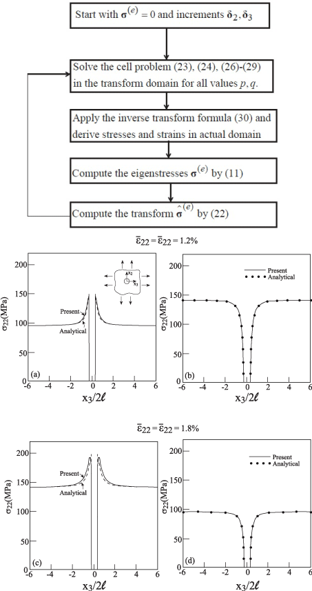
Figure 2: Elastoplastic material of the Ramberg-Osgood type with an
embedded cavity, subjected to a remote biaxial strain loading. Comparison
between the response along x3 at x2 = 0 between the present and
Ishikawa (1975) analytical solution exhibiting σ22 vs. x3 and σ33 vs. x3.
, both with = 0.
    E(GPa)
    ν
    Y (MPa)
    a
    n


    5.2
    0.35
    157.6
    3/7
    4


    E, ν, Y , a and n denote the Young’s modulus,    Poisson’s ratio, yield stress and two parameters, respectively.
Table 1: The parameters of the Ramberg-Osgood elastoplastic material.
It should be noted that the selection of M2 = M3 = 8 as the number of cells results in a ratio of about 60 between the size of the considered region 2H = 2L and the cavity radius a which is sufficiently high.
Applications
In the following applications, results are shown in which an elastoplastic aluminum alloy whose behavior is governed by the incremental classical plasticity, Equation (4), is employed to form the inelastic phase. The parameters of this elastoplastic linear hardening material are given in Table 2.
    E(GPa)
    ν
    Y (MPa)
    H(GPa)


    68.3
    0.3
    371.5
    23


    E, ν, Y and H denote the Young’s modulus, Poisson’s ratio, yield stress and hardening, respectively.
Table 2:  The parameters of the elastoplastic aluminum alloy with linear hardening
material.
Figure 3 shows the response of an infinite elastoplastic aluminum alloy in which a cavity of radius a/(2h) = 0.28 is embedded. This system is subjected to a far-field uniaxial strain loading which is incrementally applied reaching the final value of For a transverse traction-free , the component is determined at any stage of loading by the HFGMC model for a homogeneous elastoplastic material. This figure shows the elastoplastic variations of the σ22 along x3 at x3 = 0 at the final stage of loading together with the equivalent plastic strain whose increment is given by
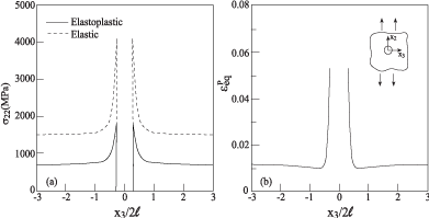
Figure 3: The response along x3 at x2 = 0 of elastoplastic material
with an embedded cavity, subjected to uniaxial strain loading of
.
This figure also shows, for a comparison, the corresponding response in the special case of perfectly elastic aluminum. Obviously, the cavity forms a stress concentrator which in the perfectly elastic case generates a stress concentration factor equal to 3 for normal stress in the loading direction. The ratio between σ22 at the edge of the cavity and the far-field value in this latter case shows that the stress concentration factor is about 2.8 as compared to the theoretical value of 3. As expected, the elastoplastic results predict a far lower value of about 2. The graph of the equivalent plastic strain indicates that the intensity of the plastic field is concentrated near the edges of the cavity and decays rapidly away from it.
Similarly, the response to a biaxial strain loading of the infinite aluminum alloy with embedded cavity is shown in Figure 4. Here the far-field strain components are incrementally increased up to 0.02 together with . The stress concentration factor in the elastic case provides the value of about 1.9 as compared to the theoretical value of 2. The corresponding elastoplastic value is seen to be about 1.6.
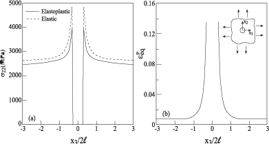
Figure 4: The response along x3 at x2 = 0 of elastoplastic material with an
embedded cavity, subjected to biaxial strain loading of
with .
Finally, the response of the infinite aluminum alloy with embedded cavity which is subjected to a biaxial loading of the form is shown in Figure 5. Here, the elastic and elastoplastic stress concentration factors are about 3.9 (theoretically 4) and 3.25, respectively.
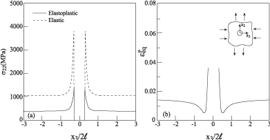
Figure 5: The response along x3 at x2 = 0 of elastoplastic material with an
embedded cavity, subjected to biaxial strain loading of
with .
The next two applications concern with a periodic unidirectional boron/aluminum metal matrix composite in which one of the elastic boron fibers is either completely lost (D = 1) thus forming a cavity, or his Young’s modulus deteriorated to one half of its original value (D = 0.5). These two situation might caused by a production defect or damage during service. The properties of the boron fibers are given in Table 3 and the fiber volume ratio is vf = 0.25. Figure 6(a) shows the variations of σ22 along x3 at x2 = 0 of the boron/aluminum composite with a missing filer at the final stage of uniaxial strain loading of . The other far-field strain component is determined by the HFGMC modeling of an unperturbed periodic unidirectional boron/aluminum metal matrix composite by imposing the condition that σ33 = 0 . Figure 6(b) and the corresponding variations of the equivalent plastic strain reveal that the effect of missing fiber is confined to the vicinity of the cavity with a rapid decay away from the defect location. Figure 6(c) shows a similar behavior when the aluminum matrix is assumed to be perfectly elastic.
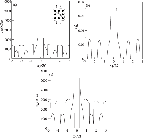
Figure 6: The response along x3 at x2 = 0 of boron/aluminum elastoplastic
composite (vf = 0.25) with a missing fiber, subjected to uniaxial strain loading
of
assuming perfectly elastic
aluminum.
    E(GPa)
    ν


    400
    0.2


    E and ν denote the Young’s modulus    and Poisson’s ratio,    respectively.
Table 3: The elastic properties of the boron.
The corresponding response of the boron/aluminum metal matrix composite in which the value of the Young’s modulus of a single boron fiber is reduced from 400GPa to 200GPa (e.g., by an imperfect bonding) is shown in Figure 7. The first two parts of this figure indicates that the effect of this defect is quite minor in the elastoplastic case, but Figure 7(c) in which the aluminum alloy is assumed to behave elastically a small stress deterioration can be detected across the defective fiber.
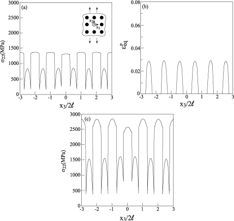
Figure 7: The response along x3 at x2 = 0 of boron/aluminum elastoplastic
composite (νf = 0.25) with a half missing fiber, subjected to uniaxial strain
loading of
.
assuming perfectly elastic aluminum.
Thus far, the effects of cavities, missing and partially missing fibers have been investigated. Presently, the effect of cracks in homogeneous, fiber reinforced and layered metal matrix composites are addressed.
Consider a single crack in the infinite aluminum alloy which is subjected to a far-field uniaxial strain . The length of the crack is 2a/(2l) = 0.5. The resulting σ22 and variations along the crack line x3 at x2 = 0 are shown in Figure 8(a) and (b).
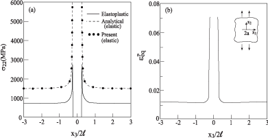
Figure 8: The response along x3 at x2 = 0 of elastoplastic material
with an embedded crack, subjected to uniaxial strain loading of
. (a) Comparison with the perfectly elastic cases
(present and analytical) of .
Also shown is the response in the special case when the aluminum is assumed to be perfectly elastic. Here an analytical solution is available, e.g. Sneddon [12], which is compared with the prediction of the present approach in this special elastic case. This comparison reveals an excellent agreement. The reduction of the magnitude of the stress in the vicinity of the crack’s tip in the elastoplastic case is well observed and the sharp high values of the plastic strains there is shown in Figure 8(b).
The next application concerns with the periodic boron/ aluminum metal matrix composite (νf = 0.25) with an embedded crack of length 2a/(2l) = 0.6 along the x3-axis within the aluminum matrix. The composite is subjected to a far-field uniaxial strain . As discussed, the other strain component is determined by the HFGMC by imposing the condition σ33 = 0 . The resulting variations of σ22 and along the crack’s line are shown in Figure 9(a) and (b), respectively. Also shown in Figure 9(a) is thecorresponding variation when the aluminum is assumed to behave as a perfectly elastic material. The reduction of the magnitude of the stress in crack’s tip as compared to elastic case is noticeable. The equivalent plastic strain reaches the value of 0.22 (not shown in the figure) rendering the employed infinitesimal plasticity theory questionable there.
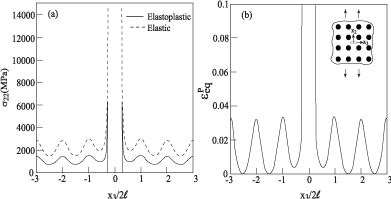
Figure 9: The response along x3 at x2 = 0 of boron/aluminum elastoplastic
composite (νf = 0.25) with an embedded crack, subjected to uniaxial strain
loading of
and
.
It should be interesting to show the distribution of the equivalent stress σeq and plastic strain in the vicinity of the crack. These are shown in Figure 10(a) and (b), respectively, in the region -2 = x2/ (2h) = 2, -2 = x3/(2l) = 2. These two figures well display the resulting effect of the crack on its surrounding region of fibers and matrix. For comparison, Figure 10(c) shows the corresponding equivalent stress distribution when the aluminum matrix is assumed to behave elastically. Note that the scale of the plot is twice the scale of the elastoplastic case.
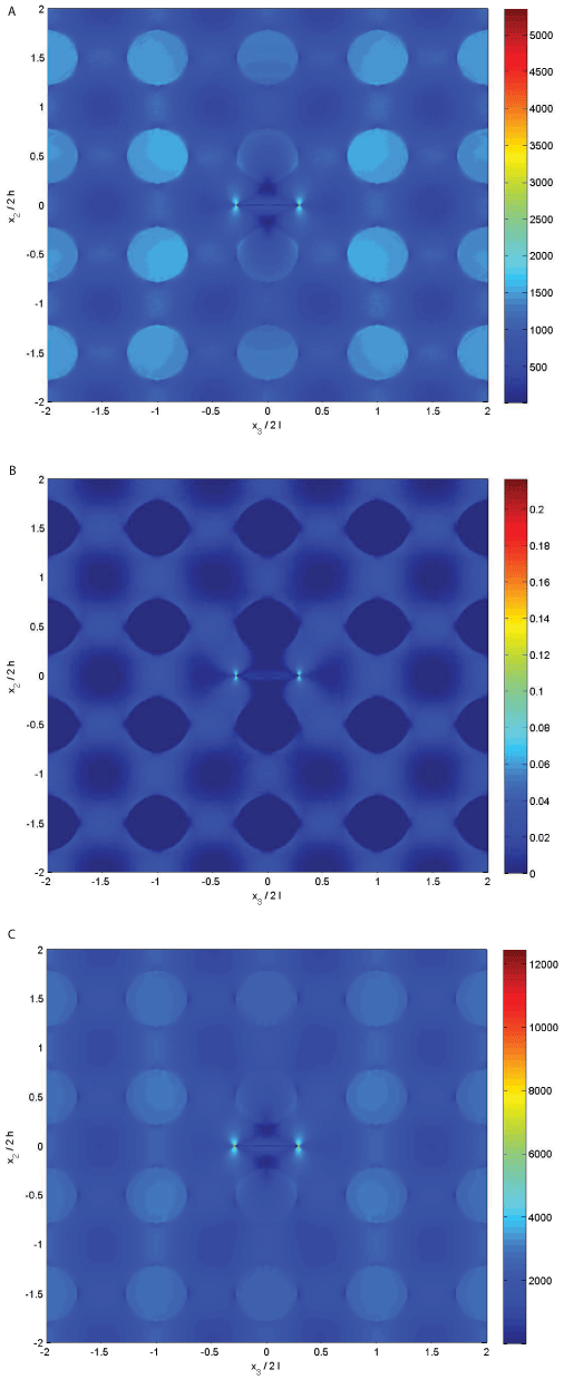
Figure 10: Field distribution of boron/aluminum elastoplastic composite (vf =
0.25) with an embedded crack in the region -2 = x2/(2h) = 2, -2 = x3/(2l) = 2. The
composite is subjected to uniaxial strain loading of
.
(a) The distribution of the equivalent stress σeq, (b) of the equivalent strain
Σeq and (c) The distribution of the equivalent stress σeq assuming a perfectly
elastic aluminum.
Our last application of the present theory concerns with the effect of a broken ceramic layer in periodically ceramic/aluminum layered composite. The elastic Al2O3 ceramic layer is characterized in Table 4. The composite is subjected to a far-field uniaxial strain and other applied strain component is determined by the HFGMC analysis by imposing the condition σ33 = 0 . Comparisons between the variations of σ22 along the crack’s line are shown in Figure 11 of the elastoplastic and elastic cases. In this figure, the widths of the ceramic and aluminum layer are equal so that the crack’s length is 2a/(2l) = 0.5.
    E(GPa)
    ν


    380
    0.2


    E and ν denote the Young’s modulus    and Poisson’s ratio,    respectively.
Table 4: The elastic properties of the Al2O3 ceramic material
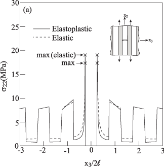
Figure 11: The response along x3 at x2 = 0 of periodically layered Al2O3/
aluminum elastoplastic composite (νf = 0.5) with an embedded crack in
the ceramic phase. The composite is subjected to uniaxial strain loading of
. The figure shows a comparison of σ22 vs. x3
with the perfectly elastic case.
Let us consider a very thin aluminum layer such that the length of the crack in the broken ceramic layer is 2a/(2l) = 0.95. The resulting comparison between the variations of σ22 along the crack’s line is shown in Figure 12(a) for the elastoplastic and elastic aluminum layer. More interesting is distribution of the equivalent plastic strain in the region -2 = x2/(2h) = 2, -2 = x3/(2l) = 2. This is shown in Figure 12(b) where reaches the value of 0.45 in the vicinity of the crack’s tip. In addition, the spread of plasticity over quite an extended region along the aluminum layer is notable.
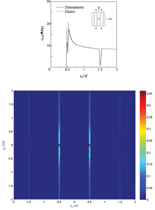
Figure 12: (a) The response along x3 at x2 = 0 of periodically layered Al2O3/
aluminum elastoplastic composite (νf = 0.95) with an embedded crack in
the ceramic phase. The composite is subjected to uniaxial strain loading
of
. The figure shows a comparison of σ22 vs. x3
with the perfectly elastic case. (b) The resulting equivalent plastic strain
distribution in the region -2 = x2/(2h) = 2, -2 = x3/(2l) = 2.
Asymptotic fracture analysis of the considered case of a very thin elastoplastic layers sandwiched between brittle elastic ones was performed by Chan et al. [13]. In this latter work a transverse crack in an elastic layer of thickness 2w was terminated at the plastic zone which was modeled by open or closed cracks of length 2d developed within elastoplastic layers, thus forming an H-crack configuration. It was found, in particular, that in the case of shear traction- free closed cracks in the plastic zone of the size characterized by the ratio d/w = 0.5, the stress concentration factor for the tensile stresses in the brittle layer adjacent to the cracked one is about 2. Inspection of the results in Figure 12 obtained in the present investigation shows that they confirm with Chan et al. [13] finding.
Conclusion
A method for the modeling of localized damage in elastoplastic composites with periodic microstructure has been presented. As a result of the localization effects (perturbations) the periodicity is lost and a repeating unit cell cannot be identified anymore. The method is based on the combination of three distinct types of analyses, namely the representative cell method, the higher-order theory for inelastic composites and the high-fidelity generalized method of cells micromechanical analysis which is needed for the determination of the far-field boundary conditions.
The representative cell method has been previously applied to solve linear and nonlinear problems, but the present method enables for the first time the analysis of elastoplastic materials. To this end, the plasticity effects are represented in the form of eigenstresses which are distributed over the entire region. In addition, these eigenstresses include the perturbation effects which are distributed over the damaged regions. The method has been applied in various cases for the prediction of the field distributions in elastoplastic materials and metal matrix composites with fiber loss and crack. Finally, the elastoplastic field in ceramic/aluminum layered composite in which a single ceramic layer is broken has been determined. Results confirm with a previously derived asymptotic analysis [13]. Presently, results for normal loading have been presented. Shear loading can be carried out in the same manner.
The present approach can be extended to the analysis of elasticviscoplastic composites with a localized damage by changing the flow rule of the elastoplastic matrix, Equation (4), to a viscoplastic one. In addition, although the present analysis has been confined to isothermal conditions, the inclusion of temperature effects in the eigenstresses can be easily performed, see Ryvkin and Aboudi [5] for the case of H-cracks in thermoelastic composites. Another possible general-ization is to allow the damage to evolve with the applied loading. Thus instead of applying an a priori a constant damage (e.g., D = 0.5 in the previously discussed case of a boron fiber with a reduced Young’s modulus), an evolution law can be adopted which according to Lemaitre and Desmorat [10] has the form
where y is the energy release, S and s are material parameters. Finally, extension to inelastic metal matrix composites with triply periodic microstructure (short-fiber composites) which include localized damage that appears in several locations is possible.
Acknowledgment
The first author is grateful for the support of the German-Israel Foundation (GIF) under contract 1166-163.
References
- Aboudi J, Ryvkin M. The effect of localized damage on the behavior of composites with periodic microstructure. Int J Engng Sci. 2012; 52: 41-55.
- Ryvkin M, Nuller B. Solution of quasi-periodic fracture problems by the representative cell method. Comp Mech. 1997; 20: 145-149.
- Aboudi J, Ryvkin M. The analysis of localized effects in composites with periodic microstructure. Philos Trans A Math Phys Eng Sci. 2013; 371: 20120373.
- Aboudi J, Arnold SM, Bednarcyk BA. Micromechanics of Composite Materials: A Generalized Multiscale Analysis Approach. Elsevier, Oxford, UK. 2013.
- Ryvkin M, Aboudi J. Stress redistribution due to cracking in periodically layered composites. Eng Fract Mech. 2012; 93: 225-238.
- Aboudi J. Field distributions in cracked periodically layered electro-magneto-thermo- elastic composites. J Intell Mater Sys Struct. 2012; 24: 381-398.
- Aboudi J. The effect of localized internal defects on the field distributions of electrostrictive composites. Int J Engng Sci. 2014; 75: 135-153.
- Ishikawa H. Stresses in the plastic range around a circular hole in an infinite sheet subjected to equal biaxial tension. J Appl Math Mech (ZAMM). 1975; 55: 171-178.
- Mendelson A. Plasticity: Theory and Applications, MacMillan, New York. 1968.
- Lemaitre J, Desmorat R. Engineering Damage Mechanics, Springer, Berlin. 2005.
- Budiansky B, Mangasarian OL. Plastic stress concentration at a circular hole in an infinite sheet subjected to equal biaxial tension. J Appl Mech. 1960; 27: 59-64.
- Sneddon IN. Fourier Transforms. McGraw Hill, New York. 1951.
- Chan KS, He MY, Hutchinson JW. Cracking and stress redistribution in ceramic layered composites, Mater. Sci Eng. 1993; A167: 57-64.